


7
http://www.national.com
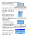
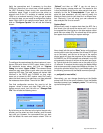
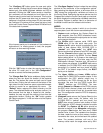
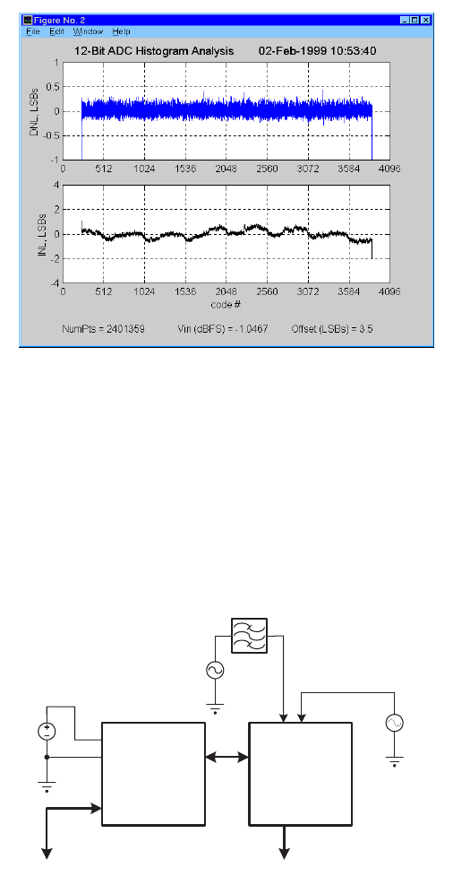
In this example, we have captured data from a 12-Bit
ADC. Remember that the data that we are plotting is the
bin count information. The ADC output codes that were
exercised ranged from code 236 to code 3865. The maxi-
mum count was set to 16384 (with DIP switches 4 and 5
OFF) and for this particular data record the maximum
count was reached at the ADC output code of 3864. To
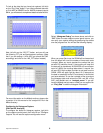
analyze the converter’s linearity, you can left click on the
“DNL_INL”
button, and you will see the following
analysis window:
For more information about this analysis technique,
please refer to Section IV of this document, the com-
ments in the DNL_INL script file, or the IEEE Standard for
Digitizing Waveform Recorders (IEEE Std 1057-1994).
Section III. Capturing Data from the
Diversity Receiver Chipset (DRCS)
Evaluation Board
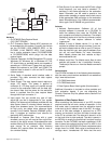
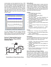
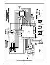
Diversity Receiver Chipset Evaluation Setup
Getting Started
To use the Data Capture board to capture data from
National’s DRCS Evaluation Board, you will need the fol-
lowing hardware, software, and documentation. Several
analysis tools are provided in the form of Matlab scripts.
It will prove helpful if the user has some familiarity with
the CLC5902 data sheet and the Diversity Receiver Eval-
uation Board User Manual document.
Hardware
1. CLC730093 Data Capture Board.
(CLC-CAPT-PCASM)
2. CLC730090 DRCS Evaluation Board.
(CLC-DRCS-PCASM)
3. DC Power Supply - The DRCS Evaluation and
Capture Board combination require +5V at >1A.
4. An IBM-Compatible Personal Computer running
Windows 95, Windows 98, or Windows NT with a
serial port capable of 115,200 baud.
5. Serial data cable to connect the data capture board
to the PC.
6. Low noise, filtered, IF Signal source for analog input
to DRCS.
7. OPTIONAL - Low jitter clock source (10 - 16dBm
sinewave) if DRCS crystal oscillator is removed.
Software
1. “Capture.exe” - Contained in the provided CDROM.
2. Data storage space on PC hard drive (default path &
name = “c:\temp\data.dat”).
3. Matlab (version 5.1 or higher) to run analysis routines.
Documentation
The following applicable documents can be found on the
provided CDROM, with the most current versions avail-
able on our website at http:// www.national.com:
1. CLC5526 - Data sheet for the Digitally controlled
Variable Gain Amplifier (DVGA).
2. CLC5956 - Data sheet for the 12-bit, 65MSPS, IF
sampled ADC.
3. CLC5902 - Data sheet for the Dual Digital Tuner/
AGC (DDC/AGC).
4. Diversity Receiver ChipSet Evaluation Board User’s
Manual (for CLC-DRCS-PCASM).
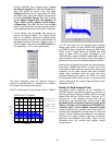
General Description and Program Options
Data from the Diversity Receiver ChipSet (DRCS)
Evaluation Board can be captured from either of its two
serial outputs, its parallel outputs, or its debug outputs.
The serial in-phase and quadrature-phase data can
also be captured simultaneously for quadrature data
analyses. The Data Capture Board always returns 32,768
BPF
Ain1
Ain2
CLK
VCC
GND
OPTIONAL
CLOCK SOURCE
FILTERED
I.F. SOURCE
+5V
VCC
(2A)
10-16dBm
To PC Serial
COMM PORT #1
64P I/O
CONNECTOR
DRCS
Evaluation
Board
Data
Capture
Board
Serial I/O
To PC Serial
COMM PORT #2