


Chapter 2. Architecture and technical overview 23
2.1.4 CMOS, copper, and SOI technology
The POWER5 processor design is a result of a close collaboration between IBM Systems and
Technology Group
and IBM Microelectronics technologies that enables IBM Sserver p5
systems to give customers improved performance, reduced power consumption, and
decreased IT footprint size through logical partitioning. The POWER5 processor chip takes
advantage of IBM leadership technology. It is made using IBM 0.13-
µm-lithography CMOS.
The POWER5 processor also uses copper and Silicon-on-Insulator (SOI) technology to allow
a higher operating frequency for improved performance, yet with reduced power consumption
and improved reliability compared to processors not using this technology.
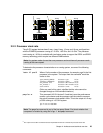
2.2 Processor cards
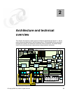
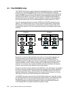
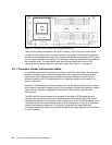
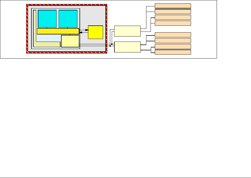
In the p5-570 system, the POWER5 chip has been packaged with the L3 cache chip into a
cost-effective Dual Chip Module (DCM) package. The storage structure for the POWER5
processor chip is a distributed memory architecture that provides high-memory bandwidth.
Each processor can address all memory and sees a single shared memory resource. As
such, a single DCM and its associated L3 cache and memory are packaged on a single
processor card. Access to memory behind another processor is accomplished through the
fabric buses. The p5-570 supports up to two processor cards (each card is a 2-way) in any
building block. Each processor card has a single DCM containing a POWER5 processor chip
and a 36 MB L3 module. I/O connects to the Central Electronic Complex (CEC) subsystem
using the GX+ bus. Each DCM provides a single GX+ bus for a total system capability of two
GX+ buses. The GX+ bus provides an interface to a single device such as the RIO-2 buses.
Figure 2-4 p5-570 DCM diagram
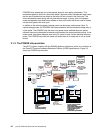
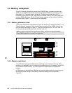
Each processor card contains a single DCM, as well as the local memory storage subsystem
for that DCM. The processor card also contains LEDs for each FRU
2
on the CPU card
including the CPU card itself. Figure 2-5 shows a processor card layout view.
2
field replacement unit
shared L2 cache
memory
controller
distributed switch
core
core
L3
cache
DCM
POWER5
SMI II
SMI II
DIMM
DIMM
DIMM
DIMM
DIMM
DIMM
DIMM
DIMM