


60 p5-570 Technical Overview and Introduction
starting on the exterior of the system (System Attention LED) and ending with an LED near
the failing Field Replaceable Unit.
For more information about replaceable units, including videos, see:
http://publib16.boulder.ibm.com/pseries/en_US/infocenter/base/new.htm#cru
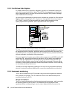
System Attention LED
The attention indicator is represented externally by an amber LED on the operator panel and
the back of the system unit. It is used to indicate that the system is in one of the following
states:
Normal state: LED is off.
Fault state: LED is on solid.
Identify state: LED is blinking.
Additional LEDs on I/O components, such as PCI-X slots and disk drives, provide status
information such as power, hot-swap, and need for service.
Concurrent Maintenance
Concurrent Maintenance provides replacement of the following parts while the system
remains running:
Disk drives
Cooling fans
Power Subsystems
PCI-X adapter cards
3.3 Manageability
Functions and tools that are provided for IBM Sserver p5 systems are described in the
following sections.
3.3.1 Advanced System Management Interface
With the system in power standby mode, or with an operating system in control of the
machine or controlling the related partition, the SP is working and checking the system for
errors, ensuring the connection to the HMC for manageability purposes.
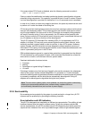
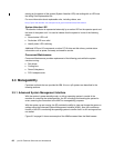
With the system up and running, the SP provides the ability to view and change the power-on
settings using the Advanced System Management Interface (ASMI). Also, the surveillance
function of the SP is monitoring the operating system to confirm that it is still running and has
not stalled.
Figure 3-2 on page 61 shows an example of the ASMI accessed from the Web browser.