


24 p5-570 Technical Overview and Introduction
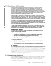
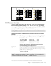
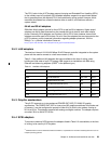
Figure 2-5 Processor card with DDR1 memory socket layout view
There are two system backplanes in the p5-570 system. A GX+ bus planar, which docks
vertically into the system planar, is always present in the system. The processor cards dock
directly into this backplane from the front. A horizontal backplane exists below the CPU cards
that is co-planar with the I/O backplane. This backplane routes the vertical fabric bus between
the processor cards. This backplane is also used for power distribution from the CPU
regulators that are housed next to the processor cards. (See Figure 1-1 on page 4.)
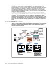
2.2.1 Processor drawer interconnect cables
In combined systems that are made of more than one p5-570 building block, the connection
between processor cards in different building blocks is provided with a processor drawer
interconnect cable. Different processor drawer interconnect cables are required for the
different numbers of p5-570 building blocks that a combined system can be made of, as
shown in Figure 2-6.
Because of the redundancy and fault recovery built-in to the system interconnects, a drawer
failure does not represent a system failure. Once a problem is isolated and repaired, a system
reboot may be required to reestablish full bus speed, if the failure was specific to the
interconnects.
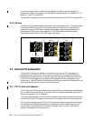
The SMP fabric bus that connects the processors of separate p5-570 building blocks is
routed on the interconnect cable that is routed external to the building blocks. The flexible
cable attaches directly to the processor cards, at the front of the p5-570 building block, and is
routed behind the front covers (bezels) of the p5-570 building blocks. There is an optimized
cable for each drawer configuration. The Figure 2-6 illustrates the logical fabric bus
connections between the drawers, and shows the additional space required left of the bezels
for rack installation.