


Chapter 2. Architecture and technical overview 27
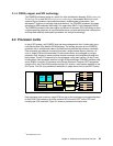
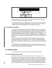
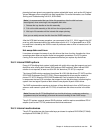
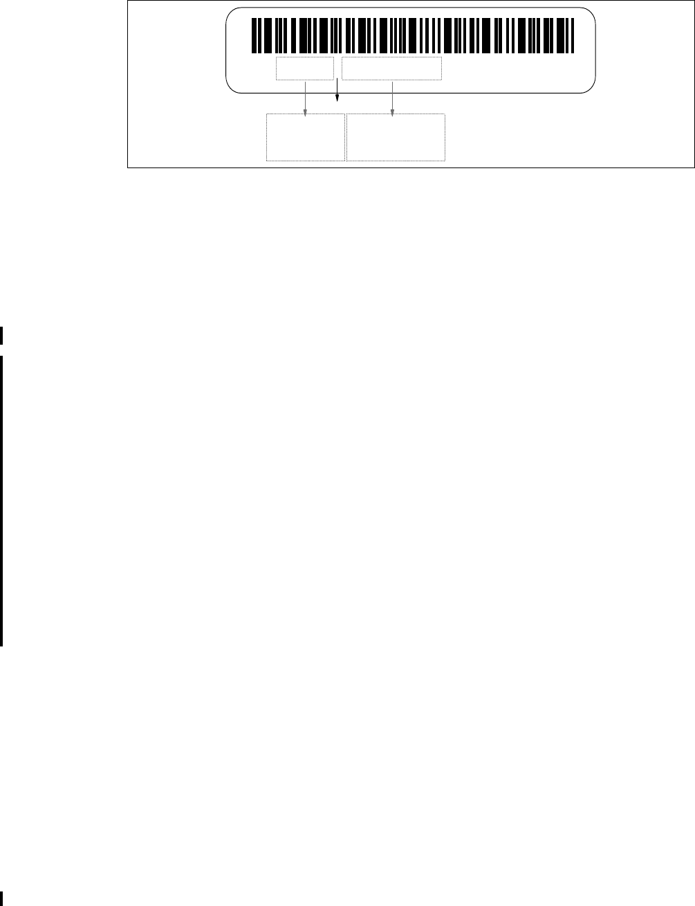
Figure 2-8 IBM memory certification label
Sometimes OEM vendors attach a label to their DIMMs that reports the IBM memory part
number but not the barcode or the alphanumeric string.
In case of system failure caused by OEM memory installed in the system, the first thing to do
is to replace the suspected memory with IBM memory, then check whether the problem is
corrected. Contact your IBM representative for further assistance if needed.
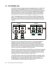
2.3.3 Memory throughput
The memory subsystem throughput is based on the speed of the memory, not the speed of
the processor. An elastic interface, contained in the POWER5 chip, buffers reads and writes
to and from memory and the processor. On DDR1 cards, there are two SMIs, each with a
single 8 byte read and 2 byte write DDR bus to the processor on each processor card. A DDR
bus allows double reads or writes per clock cycle. If 266 MHz memory is installed, the
throughput is (16 x 2 x 266.5) + (4 x 2 x 266.5) or 10660 MB/second or 10.41 GB/second per
processor card. For a building block with two processor cards, this value is doubled, or 20.82
GB/second.
DDR2 processor cards contain an additional set of two SMIs to manage the increased
throughput. However in this configuration the paths are 4 bytes for read operations and 2
bytes for write. Therefore the throughput is (4 + 2) * 4 * 1066 = 24.98 GB/s or 49.96 GB/s for
a 4-way node. These values are maximum theoretical throughputs for comparison purposes
only.
The POWER5 processor’s integrated memory controller further reduces latency over the
previous outboard controller on POWER4 systems to the SMI chips by requiring fewer cycles
in order to set up memory addressing in the hardware.
2.4 System buses
The following sections provide additional information related to the internal buses.
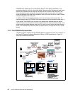
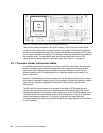
2.4.1 RIO-2 buses and GX+ card
Each DCM provides a GX+ bus that is used to connect to an I/O subsystem or Fabric
Interface card. In a p5-570 drawer, there are two GX+ buses, one from each processor card.
Each p5-570 has one GX slot with a single GX+ bus. The GX+ slot is not active unless the
second processor card is installed. It is not required for CUoD processor cards to be activated
in order for the associated GX+ bus to be active. The p5-570 provides two external RIO-2
ports, which can operate up to 1 GHz. An add-in GX+ adapter card (Remote I/O expansion
card, FC 1800) adds two more RIO-2 ports. When this card is installed, PCI adapter slot 6
11S1234567YL12345678901 FRU P/N EC Level
Seven digits
IBM part number
Twelve digits
IBM plant identificator
and part serial number
separator