


26 p5-570 Technical Overview and Introduction
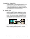
2.3 Memory subsystem
The p5-570 memory controller is internal to the POWER5 chip. It interfaces to either two
(DDR1) or four (DDR2) SMI-II buffer chips and 8 pluggable DIMMs per processor card, as
described in 2.2, “Processor cards” on page 23. The minimum memory for a p5-570
processor-based system is 2 GB. The maximum installable memory is 512 GB (using DDR1
memory DIMM technology). The p5-570 total memory depends on the number of available
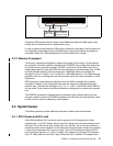
processor cards. Figure 2-7 shows memory slot availability.
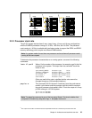
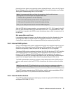
2.3.1 Memory placement rules
The memory features that are available for the p5-570 at the time of writing are listed in 1.3.2,
“Memory features” on page 6. Each memory feature consists of four DIMMs, or quad, and
must be installed according to Figure 2-7. The first quad slots are J0A, J1A, J0C, and J1C.
For the second quad, the slots are J0B, J1B, J0D, and J1D.
Figure 2-7 Memory placement for the p5-570, DDR1 card
2.3.2 Memory restriction
The p5-570 does not support OEM memory, and there is no exception to this rule. OEM
memory is not certified for use in pSeries and in the IBM Sserver p5 systems. If the p5-570
is populated with OEM memory, you could experience unexpected and unpredictable
behavior.
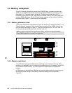
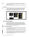
All IBM memory is identified by an IBM logo and a white label printed with a barcode on top
and an alphanumeric string on the bottom, created according to the rule reported in
Figure 2-8.
Note: A quad must consist of a single feature (that is, made of four identical DIMMs).
Mixing DIMM capacities in a quad is not supported.
DCM
2-way
J0C
J0B
J1D
J1B
J0D
J0A
J1C
J1A
First quad
Second quad
SMI II
SMI II
Heat Sink