


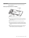
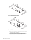
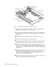
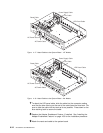

Fan Cable
LED Panel Cable
Power Supply Cable
Reset Cable
AC Power Ground
AC Power Cable
Figure 4-13. Cables Attached to the System Board - 24x Models
1 Remove any optional adapters, if installed. See “Removing the Optional
Adapter” on page 4-38 for the removal procedure.
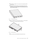
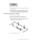
2 Remove the power supply cable connector by pulling out the retaining clips
with your fingers or a screwdriver and then rocking it from front to back as
you pull up.
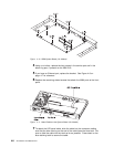
3 Remove the fan cable by rocking it from front to back as you pull up.
4 Remove the reset card cable from the system board.
5 Remove the Adapter Enablement Feature, if installed. See “Removing the
Adapter Enablement Feature” on page 4-36 for the removal procedure.
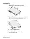
6 Remove the LED panel cable by using a screwdriver on either side of the
connector to lift the blue retaining latch. Pull the cable from the latch. Note
as you remove this cable that the blue coloring on the end of the cable faces
the blue latch.
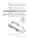
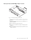
7 Remove the second service port, if one is installed. See “Removing the EIA
232 Service Port Feature in Models 14T and 24x” on page 4-40 or
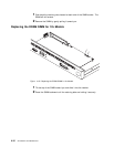
“Removing the 14.4 Kbps Modem Port Feature in Models 14T and 24x” on
page 4-41 for the appropriate procedure.
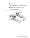
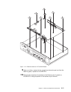
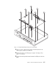
8 Remove the system board retainer screws using a nut driver. Figure 4-14 on
page 4-11 shows the location of the retainer screws.
4-10 2210 Service and Maintenance