| to delete any virtual interfaces, for example, dial circuits, associated with the
| adapter prior to removing the adapter. The talk 6 delete interface command
| deletes the interface you explicitly state in the command line. The interface in
| current use will not be deleted unless you specify that interface name in the
| command line.
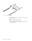
If the guide rails are visible, the feature is installed and you can continue the instal-
lation at “Installing Optional Adapters” on page 4-36.
If the guide rails are not visible, you should begin the installation at “Installing the
Adapter Power Supply.”
Installing the Adapter Power Supply
1 Remove the cover as directed in “Removing the Cover” on page 4-2, if not
already removed.
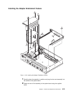
2 Remove the power supply cover and keep the three fastening screws. See
“Removing the Base Power Supply for 14T and 24x Models” on page 4-22
for detailed instructions.
3 Turn over the cover.
4 Place the insulator inside the top of the cover.
5 Place the power supply on the insulator and fasten it in position to the top of
the power supply cover using the four securing screws.
6 Attach the dc power cable to the power supply and feed the cable through
the access slot.
7 Attach the ac power cable to the power supply and replace the cover over
the existing power supply, using the original screws. Make sure that the lip
of the cover goes under the lip of the frame.
Assembling the Riser Card
Refer to “Handling Static-Sensitive Devices” on page 4-2 before removing or
installing the riser card to the system board.
Chapter 4. Removal and Replacement Procedures 4-33


