


DeviceNet to PLCs or Devices
16
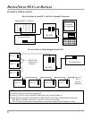
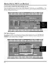
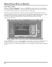
The DN-3000 supports up to a total of 64 bytes (32 words) of combined Input and Output data. Each
word (2 bytes) of Input or Output data can be configured to exchange data with any one valid data register
in any one of the PLCs/Devices connected to port 2 of the DN-3000 (see “CONFIGURING PORT 2” for
PLC/Device Protocol and communication parameters).
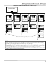
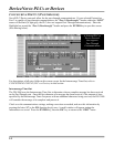
Use Command Block
In some projects it may be necessary to be able to access more than just the 32 PLC/Device registers that
can be configured in the Input and Output data. A Command Block reserves the first 4 words of Output
data for commands, and the first 4 words of Input data for command results. This reduces your total
number of words that can be used for register data to 24 words, but adds flexibility by allowing your
DeviceNet Host to issue commands to the DN-3000 to access any valid data registers in any PLC or
Device connected to port 2 of the DN-3000. Commands are issued by moving a command code,
PLC/Device address, file number (Allen-Bradley PLCs only), register number, and data into the first 4
words of the Output data (see “COMMAND BLOCK”).
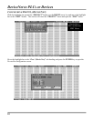
Use Diagnostics
Diagnostics allows the DeviceNet Host to monitor PLC/Device connections to the DN-3000. The first
word of the Input data following the Command Result Block (if any) will be reserved for Diagnostics if
this option is selected. The DN-3000 keeps track of the connection status with each PLC/Device address
(0-255). Whenever an attempt to communicate with a PLC/Device is successful, the connection status for
that PLC/Device is set to ‘0’. Whenever an attempt to communicate with a PLC/Device is unsuccessful,
the connection status for that PLC/Device is set to ‘1’. Of course, returning 256 status bits would require
16 words of Input data (half of the available I/O data). Instead, only 16 bits (1 word) of are returned.
Each of the 16 bits of the Diagnostics word represents the status of 16 PLC/Device addresses, as follows:
bit 0 represents PLC/Device addresses 0, 16, 32, 48, 64, etc.; bit 1 represents PLC/Device addresses 1, 17,
33, 49, 65, etc.; and so forth. If the status of any of the PLC/Device addresses represented by a bit is ‘1’,
that bit will contain a ‘1’, otherwise, that bit will contain a ‘0’. Note that the status of a PLC/Device is set
to ‘1’ only if the DN-3000 attempts to communicate with that PLC/Device and that attempt is
unsuccessful.
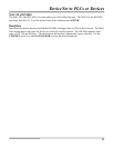
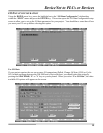
Output Data Size
This determines the number of words of Output data that will be used in your project. Output data is data
that is output from your DeviceNet Host to the DN-3000 (commands, and register data to be written to
PLCs/Devices). This is also known as the Consumed I/O Data of the DN-3000. If a Command Block is
used, it will automatically reserve 4 words of Output data. The combined size of the Input and Output
data must not exceed 32 words.
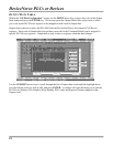
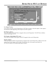
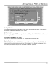
Output Data
Pressing the Output Data button brings up a window allowing you to edit the configuration of the Output
data in your project. You can press the Output Data button by clicking on it with your mouse, or moving
the focus to the button with the arrow keys and pressing the SPACEBAR. See “OUTPUT DATA
TABLE”.