


DeviceNet to Motor Drives
38
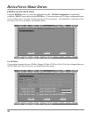
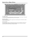
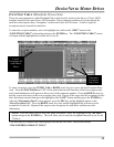
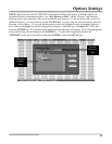
UPPER LINK CONFIGURATION (Mitsubishi Drives Only)
The “Upper Link Configuration” screen is only used with Mitsubishi Drives. To open this screen, place
the highlighted bar around the “Upper Link Table” sub-heading (within the “EDIT” menu) and press the
ENTER key. The Upper Link Table is used to select which drive or drives support Upper Parameter
Numbers. If a particular drive supports upper parameters, it must be set in this table to insure proper
communications with the motor drive.
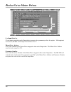
To enable the Upper Link for any drive, use the computer’s arrow KEYS to move the highlighted
brackets to the desired drive number and press the SPACE BAR. This places an “X” between the
brackets. The Upper Link Activity time-out is used by the DN-3000 to ensure the state of the link setting
in the drive when it has not had any communications with the drive for a certain period of time.
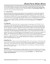
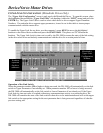
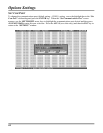
Numbers
represent
the drive
addresses
Mitsubishi’s
Upper Link
Configuration
Window
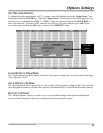
Operation of the Link Switch
When the parameter number 128 or higher is being accessed, the DN-3000 will automatically set the link
switch to Upper Parameters if not already set. When parameter number 127 or lower is being accessed,
the DN-3000 will automatically set the link switch to Lower Parameters if not already set. If the Upper
Link Activity time-out value is reached without any communications activity to a particular drive, the
DN-3000 will consider the state of the link switch for that drive to be indeterminate and will set the upper
link switch to the appropriate setting for the next parameter that is being accessed regardless of what the
previous setting was.