


Technical Information
47
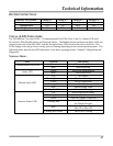
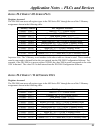
DIP SWITCH SETTINGS
OPERATING MODE Switch # 1 Switch # 2 Switch # 3 Switch # 4
Normal
Off Off Off Off
Configuration
Off Off
ON
Off
Diagnostic ON ON
Off Off
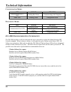
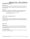
VISUAL (LED) INDICATORS
The DN3000 has 5 tri-color LEDs: 2 Communication Port LEDs (Ports 2 and 3), a Status LED and 2
DeviceNet LEDs (Module Status and Network Status). The Module Status and Network Status LEDs are
located on the side of the DN-3000, with the Network Status LED closest to the DeviceNet Port. The
LEDs change color and go from a steady glow to flashing depending on the current operating mode. The
following tables describe the LED indications in the three operating modes: Normal, Configuration and
Diagnostic.
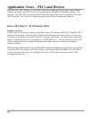
NORMAL MODE:
LED COLOR MEANING
Green Transmitting Data
Communication Port LEDs
Red Receiving Data
Green DeviceNet Initialized/Ok
Status LED
Red DeviceNet Error
Off No Power
Flashing Green Device in Standby
Green Device Operational
Flashing Red Minor Fault
Red Unrecoverable Fault
Module Status LED
Flashing Red-Green Device Self Testing
Off Not Powered/Not Online
Flashing Green Online, Not Connected
Green Link OK, Online, Connected
Flashing Red
One or more I/O Connections are in
the Timed-Out state
Red
Critical Link Failure (Duplicate
Mac ID or Bus-off)
Network Status LED
Flashing Red-Green Device Self Testing