


DeviceNet to PLCs or Devices
22
COMMAND BLOCK
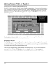
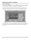
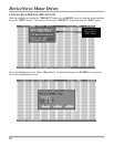
Using I/O data to update and/or monitor motor drive parameters requires very little programming in your
DeviceNet Host device – the configuration of the DN-3000 specifies which PLC/Device registers are
mapped to which words of I/O data. However, you can only access a total of 32 registers this way, and
those registers are fixed when the DN-3000 is configured. If your application requires that you access
more than 32 registers, you must either use multiple DN-3000s, or use a Command Block.
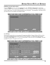
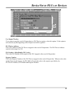
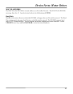
A Command Block allows your DeviceNet Host to issue commands at run-time to read or write any valid
register in any PLC/Device connected to Port 2 of the DN-3000. The Command Block reserves the first 4
words of Output data for commands issued by the Host, and the first 4 words of Input data for the results
of those commands (along with any returned data). Commands are issued by moving a PLC/Device
Address, File Number, Register Number, any required Register Data (for write commands only), and a
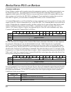
Command code into the Command Block, as follows:
15 14 13 12 11 10 9 8 7 6 5 4 3 2 1 0
word 1
PLC/Device Address (0-255) 0 0 0 0 Command
word 2
File Number
word 3
Register Number
word 4
Register Data (write command only)
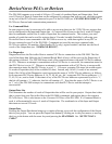
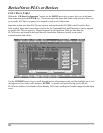
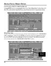
The DN-3000 looks for changes in the Command Block data to determine when there is a new request to
be processed, “throwing out” any invalid commands received. Valid Commands are 1 (read) and 2
(write). To ensure that partial commands are not processed (in systems where it is possible that Output
data could be sent by the host before all 4 words of data have been moved into the command block), you
should set the Command to 0 (indicating no command), then place the data in words 2-4, and only set the
Command to 1 or 2 after all of the other data is in place. After a command has been processed by the DN-
3000, it will “echo” the command in the Command Result Block in the Input data, and set the Result Code
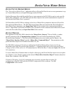
and any Returned Register Data, as follows:
15 14 13 12 11 10 9 8 7 6 5 4 3 2 1 0
word 1
PLC/Device Address 1 Result Code Command
word 2
File Number
word 3
Register Number
word 4
Returned Register Data (read command only)
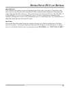
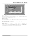
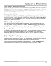
If a read command (1) was issued, the Returned Register Data will contain the register data read from the
specified PLC/Device. If a write command (2) was issued, the Returned Register Data will be the same
as for the issued command. The Result Code indicates the result of processing the issued command.
Valid Result Codes are as follows:
Result Code Meaning
0 Command was completed successfully.
1 DN-3000 could not communicate with indicated PLC/Device.
7 Command was invalid.