


Technical Information
48
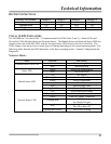
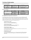
CONFIGURATION MODE:
LED COLOR MEANING
Communication Port # 3
LED
Flashing Red-Green Communicating with Computer
Status LED Flashing Green Configuration Mode
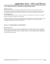
DIAGNOSTIC MODE:
LED COLOR MEANING
Flashing Green Port is Operational
Communication Port LEDs
Flashing Red or
Yellow
Port not Operational or Loopback
Connector not Installed
Status LED Flashing Red Diagnostics Mode
DN-3000 TROUBLESHOOTING INFORMATION
The DN-3000 performs a self-test each time the unit is powered up or when the Mode Selection DIP
Switch is changed. When it detects a failure, it will report the type of failure on the Status LED. All
failures are reported as a flash code in which the DN-3000 will flash its Status LED yellow a designated
number of times followed by a pause. The flash code will repeat itself until the unit is powered off. The
possible errors that can be reported and the recommended actions are:
2 flashes followed by a pause
Random Access Memory Failure (RAM Failure)
Send the unit in for repair (Obtain RMA number first).
3 flashes followed by a pause
Firmware stored in ROM failed checksum test (ROM Failure)
Send the unit in for repair (Obtain RMA number first).
4 flashes followed by a pause
Unit Not Configured or EEPROM failure
If transferring your project file to the DN-3000 does not correct this error, send the unit in for
repair (Obtain RMA number first).
5 flashes followed by a pause
Invalid DIP Switch Setting
Verify that the DIP Switch is properly set to a valid operating mode (See DIP Switch Settings
in this section). If the DIP Switch is properly set, send the unit in for repair (Obtain RMA
number first).