C H A P T E R 3Cable the module
14
5 Plug the SC connectors on the optic fiber cable into the RX and
TX sockets, and connect the other end of the cable to a device.
6 Check the LEDs on the 1000SX Advanced Module to verify the
links. For more information on LEDs, see Chapter 2.
Cabling to a Matrix Module in a stack of switches with redundancy
To provide total redundancy for the high-speed link, two 1000SX Ad-
vanced Modules are necessary. We recommend that you install these in
different switches from the Matrix Modules.
Note Redundancy is not possible with the 510T.
1 Connect the Matrix Modules to the Stack Interface Modules in the
primary and secondary switches as described in the Matrix Mod-
ule User Guide.
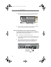
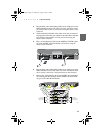
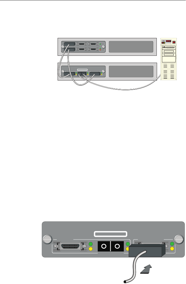
2 Plug a Stacking Cable (Intel Order Code: ES500SC) into the
Stack Interface Module connector on the 1000SX Advanced
Module, and secure it using the latches on the connector.
Matrix Module for 500 Series Switches
4
1
5
2
6
3
Module
Status
Link
Status
Internal Port
1000SX Advanced Module for 500 Series Switches
1000Base-SX
Stack Interface Module
CLASS 1 LASER PRODUCT
Server
5047
1000Base-SX
Stack Interface Module
CLASS 1 LASER PRODUCT
1000SX Advanced Module for 500 Series Switches
5048
Stacking Cable
connected to
the Matrix Module
RXTX
A23295.book Page 14 Wednesday, August 30, 2000 1:16 PM


