


C H A P T E R 3Cable the module
16
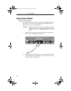
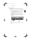
8 Plug the SC connectors on the fiber optic cables into the RX and
TX sockets, and connect the other end of the cables to a device or
group of switches with redundancy.
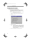
9 Use Intel Device View to ensure that the mode settings for the two
1000SX Advanced Modules are the same.
10 Check the LEDs on the 1000SX Advanced Modules to verify the
links. For more information on LEDs, see Chapter 2.
Combine bandwidth on two modules
Introduction
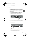
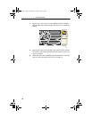
Two modules installed on the same side of separate switches in a stack
(for example, both modules in Slot A) can have their bandwidth com-
bined (known as link aggregrated) to increase the bandwidth between
this stack and another device or stack.
Note The two modules must have the same mode settings for link
aggregation to work properly. Mode settings can be checked
and changed using Intel Device View, see Chapter 4.
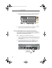
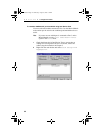
Prevent network loops
Link aggregation must be configured in Intel Device View to prevent a
loop (see Chapter 4). When two modules are installed in a stack and
connected to another single device or stack (without redundancy or link
aggregation), then a loop may be created. Note that even with spanning
tree enabled, a delay of 10 to 15 seconds may occur before the loop is
discovered.
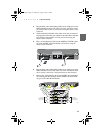
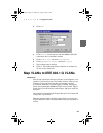
Note The 1000SX Advanced Module connected to port 3 on the
Matrix Module must be configured as the anchor port.
A23295.book Page 16 Wednesday, August 30, 2000 1:16 PM