APPENDIX B Intel Express 100BASE-TX Stackable Hub
44
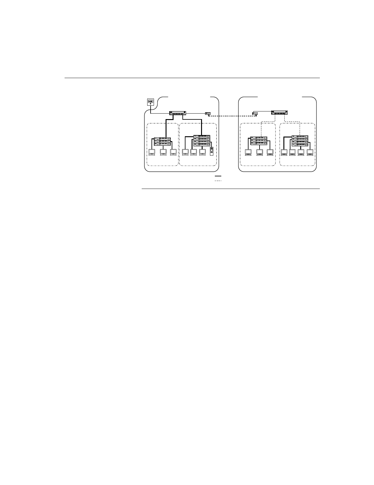
100BASE-T
workstations
100BASE-T
workstations
Stack of
100BASE-T
hubs
Stack of
100BASE-T
hubs
Stack of
100BASE-T
hubs
Stack of
100BASE-T
hubs
100BASE-TX
switching hub
100BASE-TX
switching hub
100 meter Category 5 UTP
160.8 meter fiber cable
5874.2
Router
Up to 2 km
fiber cable
(Full duplex)
Domain 1 Domain 2 Domain 3 Domain 4
Server
transceiver
1 m
1 m
transceiver
100BASE-T
workstations
100BASE-T
workstations
521.6 m total network topology
with two collision domains
400 m total network topology
160.8 m
Interconnecting repeaters and switches in multiple domains
Calculating Round Trip Collision
Delay
Calculating the round trip collision delay between all pairs of DTEs in
a 100BASE-T network ensures that the network is not violating the
CSMA/CD protocol. This calculation involves selecting the worst case
path delay (PDV) to determine if your network falls within round trip
collision requirements. The worst case path is usually the path
between the two DTEs at the opposite ends of the network and the
transmissions between them have the longest round trip time.
To qualify the DTE-to-DTE path in terms of worst-case delay, you
must ensure that the maximum length fragment contains less than 512
bits after the start of the frame delimiter. To determine if the DTE-to-
DTE paths fall within PDV requirements for a 100BASE-T network,
calculate the delay values for the following network devices:
• Link segment delay values (LSDV)
• Repeater delay values
• DTE delay values
• Safety margin value
These values can be plugged into the following formula to calculate
the worst case PDV for each path:
PDV = Sum of LSDVs + sum of repeater delays + DTE delays + safety
margin


