10 21555 PCI-to-PCI Bridge Evaluation Board User’s Guide
Introduction
1.6 Resistor Jumpers
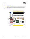
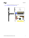
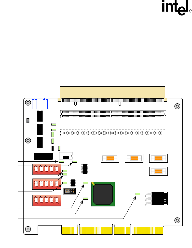
Figure 3 shows the location of the zero (0) ohm resistor configuration jumpers. They control the
clock configuration and the clamping voltage. To alter the factory configuration of the
DE1B55503, the jumpers must be soldered on or off the DE1B55503 board. See Appendix A,
“Signal and Default Information”.
Figure 3. Jumper Resistors
A8410-01
J1
E4
J9
J20
J21
R72
OPTIONAL SLOT
SLOT 1
Y1
E2
E3
J4 J6 J2
J5
E1
21555
1 2 3 4 5
1 2 3 4 5
1 2 3 4 5
J102
J101
J7
SLOT 2
R69
R93
R100
R73
R66
R68
R65
R97
R95
R91 R115
R116
R92
J8
E9
E8
E7
E5
L2
L1+


