12 21555 PCI-to-PCI Bridge Evaluation Board User’s Guide
Introduction
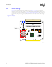
1.7 Secondary Slot Numbering and IDSEL Mapping
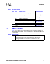
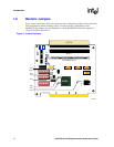
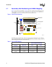
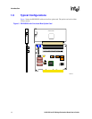
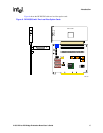
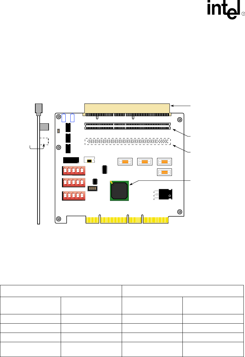
Figure 4 gives the bus slot numbering. Table 5 shows how a Product Name numbers the Local
slots in response to a Type 0 or Type 1 configuration cycle. The local bus lines s_ad<24> and
s_ad<31:28> are used as local Initilization Device Select (IDSEL) lines.
The 21555 cannot respond to Type 1 but does respond to Type 0 configuration cycles. During a
Type 0 configuration from a Local processor in the PICMG slot, the numbers change so that J7 is
counted one way but reflected as zero the other way.
Figure 4. Local PCI Slot Numbering
A8411-01
J1
E4
J9
J20
J21
OPTIONAL SLOT
PCI option and PICMG
slot - Device 13/13
PCI option and slot
Device 20/Zero (0)
SLOT 1
Y1
E2
E3
J4 J6 J2
J5
E1
21555
1 2 3 4 5
1 2 3 4 5
1 2 3 4 5
J102
J101
J7
SLOT 2
1
2
Device 8/8
Device None/17
OPTIONAL
SLOT
J8
E9
E8
E7
E5
L2
L1+
Table 5. Slot and IDSEL Mapping
Device Configuration Numbering
Physical Connector
Numbering
IDSEL Lines Type 1 Type 0
J7 (Slot 2) S_AD31 20 zero (0)
J102 (Opt. Slot) S_AD24 8 8
J101 (Slot 1) S_AD29 13 13
E2
(21555)
S_AD28 (no response) 17


