8 21555 PCI-to-PCI Bridge Evaluation Board User’s Guide
Introduction
1.4 Switch Settings
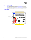
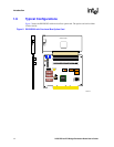
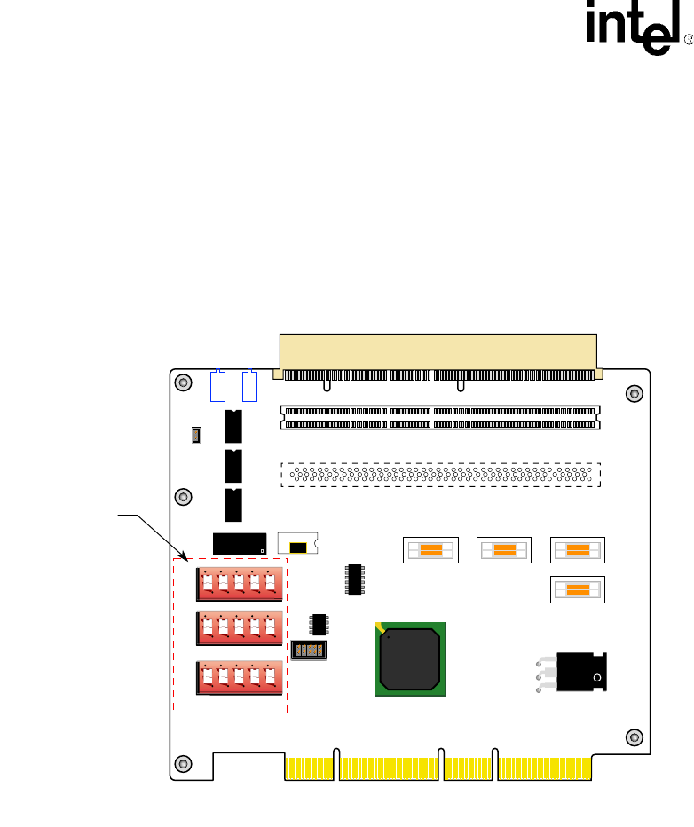
Figure 2 shows the three initialization switch packs, and Table 1 on page 9 gives a high-level
description of each switch. The switches are read at DE1B55503 power up. Further details on the
operation of these switches can be found in Chapter 3, “Optional Configurations”. The switches are
in dual-in-line (DIP) packs designated J9, J20, and J21. Each switch pack contains SW1 through
SW5.
Figure 2. Switches
A8409-01
J1
E4
J9
J20
J21
OPTIONAL SLOT
Initialization
Switches
SLOT 1
Y1
E2
E3
J4 J6 J2
J5
E1
21555
1 2 3 4 5
1 2 3 4 5
1 2 3 4 5
J102
J101
J7
SLOT 2
E9
E8
E7
E5
L2
L1+
J8


