21555 PCI-to-PCI Bridge Evaluation Board User’s Guide 13
Introduction
1.8 Interrupt Routing
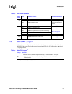
Table 6 shows the ORing of interrupts. 12 interrupts are connected to each of three secondary bus
PCI slots but four (4) interrupts are driven to the card edge. The 12 incoming interrupts must be
combined. Interrupt ORing is in accordance with the PCI-to-PCI Bridge Architecture Specification
revision 1.1.
Table 6. Interrupt ORing
Device Number
Interrupt Pin on
Device
Interrupt Pin on Board
Connector
5
(Optional slot J101)
INTA#
INTB#
INTC#
INTD#
INTB#
INTC#
INTD#
INTA#
6
(PICMG slot J101)
INTA#
INTB#
INTC#
INTD#
INTA#
INTB#
INTC#
INTD#
7
(Top slot J7)
INTA#
INTB#
INTC#
INTD#
INTD#
INTA#
INTB#
INTC#


