


21555 PCI-to-PCI Bridge Evaluation Board User’s Guide 21
Optional Configurations 3
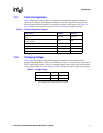
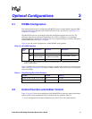
3.1 PICMG Configuration
This section describes how to configure the DE1B55503 to have a Single Board Computer (SBC)
with a PCI interface as defined in the PICMG PCI-ISA Interface Specification. See Section 1.3.1,
“Connectors” on page 6.
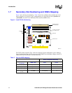
The DE1B55503 can have an intelligent subsystem installed that supports the local bus. The
intelligent subsystem is architecture independent. The 21555 can interface to any intelligent
subsystem that has a PCI interface. Connector J101 can accept an intelligent controller and operate
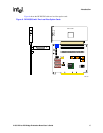
in the PICMG mode. See Figure 2 on page 8.
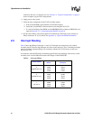
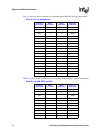
Table 10 gives the switch configuration to enable PICMG mode operation.
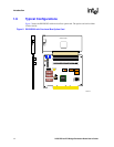
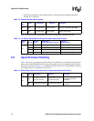
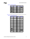
Table 11 identifies the zero ohm resistors to remove or install for the system slot to act as the clock
source. See Figure 3 on page 10. To operate an SBC controller on the local bus, the clocks must be
routed accordingly.
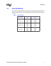
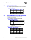
3.2 Central Function and Arbiter Control
Table 12 on page 22 shows the configuration of the DE1B55503 for internal or external arbitration.
Arbiter control can be programmed on the evaluation board by switching SW1 J21.
• In one configuration, the internal arbitration logic of the 21555 is the central function.
Table 10. J9 PICMG Switches
Switch
Pack
Switch Switch Down
a
Switch Up Description
J9
SW1 PICMG slot DB66 Secondary reset originates
SW2
PICMG
(becomes GNT2)
PCI
(S_AD24 becomes DSEL)
S_AD24 (IDSEL) originates
SW3 PICMG PCI (S_PME#)
a. J9 positions SW1, SW2, and SW3 must be down for normal PCI operation. The switches define where the RESET,
ID-SEL, and PME originate.
Table 11. Clock Routing Zero Ohm Resistors
Function Installed Removed
System slot drives s_clk_i on the 21555 R68 R73, R65
System slot provides local clock R92, R116, R69 R91, R115, R72