21555 PCI-to-PCI Bridge Evaluation Board User’s Guide 9
Introduction
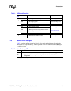
1.5 Stake-Pin Jumper
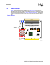
Table 2 shows the configuration and the function of the single stake-pin jumper. J8 enables the
DE1B55503 hot-swap functionality, controls operation of LED L1, and connects the l_stat signal
to a pullup resistor.
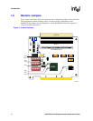
Table 1. DIP Switch Operation
Switch
Pack
Switch The Switch Controls Reference Information
J9
SW1, 2, 3 PICMG configurations. (See Chapter 3). Table 10 on page 21
SW4 PR_AD1 strapping option.
21555 Non Transparent
PCI-to-PCI Bridge User’s
Manual
SW5 PR_CS to either Flash or optional ROM socket. Table 8 on page 19
J20
SW1 PR_AD2 for SROM operation.
Table 7 on page 18
SW2 PR-AD3 for lockout bit control.
SW3 PR_AD4 for synchronous or asynchronous clocking.
Table 14 on page 22
SW4 PR_AD5 for S_CLKO operation.
SW5 PR_AD6 for Central function selection. Table 12 on page 22
J21
SW#
(1,2,3,4,5)
The REQ/GNT lines for Arbiter control.
Table 12 on page 22
Table 13 on page 22
Table 2. Stake-Pin Jumper
a
Jumper Function
J8
• When removed, the hot-swap functionality is enabled, and L1 will light.
• When installed, hot-swap functionality is disabled and the L1 LED is
extinguished.
a. No jumper is installed by the Factory default.


