


Intel
®
5100 MCH Chipset
Intel
®
5100 Memory Controller Hub Chipset for Communications, Embedded, and Storage Applications
TDG July 2008
12 Order Number: 318676-003US
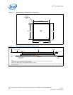
Note: These specifications apply to uniform compressive loading in a direction perpendicular
to the IHS top surface.
Note: These specifications are based on limited testing for design characterization. Loading
limits are for the package only.
3.0 Thermal Specifications
3.1 Thermal Design Power (TDP)
Analysis indicates that real applications are unlikely to cause the MCH component to
consume maximum power dissipation for sustained time periods. Therefore, in order to
arrive at a more realistic power level for thermal design purposes, Intel characterizes
power consumption based on known platform benchmark applications. The resulting
power consumption is referred to as the Thermal Design Power (TDP). TDP is the target
power level to which the thermal solutions should be designed. TDP is not the
maximum power that the chipset can dissipate.
FC-BGA packages have a poor heat transfer capability into the board and have a
minimal thermal capability without a thermal solution. Intel recommends that system
designers plan for a heatsink when using the Intel
®
5100 MCH Chipset.
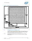
3.2 Case Temperature
To ensure proper operation and reliability of the Intel
®
5100 MCH Chipset, the case
temperatures must be at or between the maximum/minimum operating temperature
ranges as specified in Table 3. System and/or component level thermal solutions are
required to maintain these temperature specifications. Refer to Section 5.0, “Thermal
Metrology” on page 15 for guidelines on accurately measuring package case
temperatures.
4.0 Thermal Solution Requirements
4.1 Characterizing the Thermal Solution Requirement
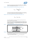
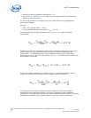
The idea of a “thermal characterization parameter” Ψ (the Greek letter Psi) is a
convenient way to characterize the performance needed for the thermal solution and to
compare thermal solutions in identical situations (in other words, heating source, local
ambient conditions, and so forth). The thermal characterization parameter is calculated
using total package power; whereas, actual thermal resistance, θ (theta), is calculated
using actual power dissipated between two points. Measuring actual power dissipated
into the heatsink is difficult, because some of the power is dissipated through a heat
transfer into the package and board.
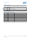
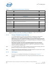
Table 3. Intel
®
5100 Memory Controller Hub Chipset Thermal Specifications
Parameter Value Notes
T
case_max
105 °C
T
case_min
5 °C
TDP
Max config
25.7 W DP FSB 1333, 2 channel DDR2 667, 3 x8 PCI Express*
TDP
Typical ATCA config
23.0 W DP FSB 1067, 2 channel DDR2 533, 3 x8 PCI Express*
TDP
Typical UP config
19.5 W UP FSB 1067, 1 channel DDR2 533, 1 x8 PCI Express*