


Intel
®
5100 Memory Controller Hub Chipset for Communications, Embedded, and Storage Applications
July 2008 TDG
Order Number: 318676-003US 15
Intel
®
5100 MCH Chipset
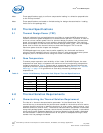
Table 4 summarizes the thermal budget required to adequately cool the Intel
®
5100
MCH Chipset in one configuration using a TDP of 25 W. Further calculations would need
to be performed for different TDPs. Because the results are based on air data at sea
level, a correction factor would be required to estimate the thermal performance at
other altitudes.
5.0 Thermal Metrology
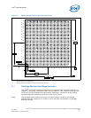
The system designer must make temperature measurements to accurately determine
the thermal performance of the system. Intel has established guidelines for proper
techniques to measure the MCH case temperatures. Section 5.1 provides guidelines on
how to accurately measure the MCH case temperatures. Section 5.2 contains
information on running an application program that will emulate anticipated maximum
thermal design power (Figure 6).
5.1 MCH Case Measurement
The Intel
®
5100 MCH Chipset cooling performance is determined by measuring the
case temperature using a thermocouple. For case temperature measurements, the
attached method outlined in this section is recommended for mounting a
thermocouple.
Special care is required when measuring the case temperature (T
C
) to ensure an
accurate temperature measurement. Thermocouples are often used to measure T
C
.
When measuring the temperature of a surface that is at a different temperature from
the surrounding local ambient air, errors may be introduced in the measurements. The
measurement errors can be caused by poor thermal contact between the thermocouple
junction and the surface of the integrated heat spreader, heat loss by radiation,
convection, by conduction through thermocouple leads, or by contact between the
thermocouple cement and the heatsink base. To minimize these measurement errors,
the approach outlined in the next section is recommended.
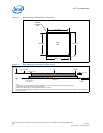
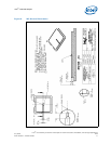
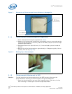
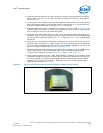
Note: The thermocouple attach example shown below is on a different package, but the
method and groove dimensions are the same. The thermocouple bead needs to be
centered on the IHS.
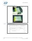
5.1.1 Supporting Test Equipment
To apply the reference thermocouple attach procedure, it is recommended that you use
the equipment (or equivalent) given in Table 5.
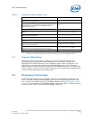
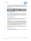
Table 4. Required Heatsink Thermal Performance (Ψ
CA
)
Device Ψ
CA
(°C/W) at T
LA
= 45 °C Ψ
CA
(°C/W) at T
LA
= 60 °C
Intel
®
5100 MCH Chipset @ 25 W 2.4 1.8