


Intel
®
5100 MCH Chipset
Intel
®
5100 Memory Controller Hub Chipset for Communications, Embedded, and Storage Applications
TDG July 2008
30 Order Number: 318676-003US
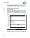
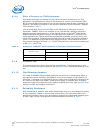
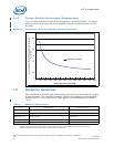
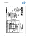
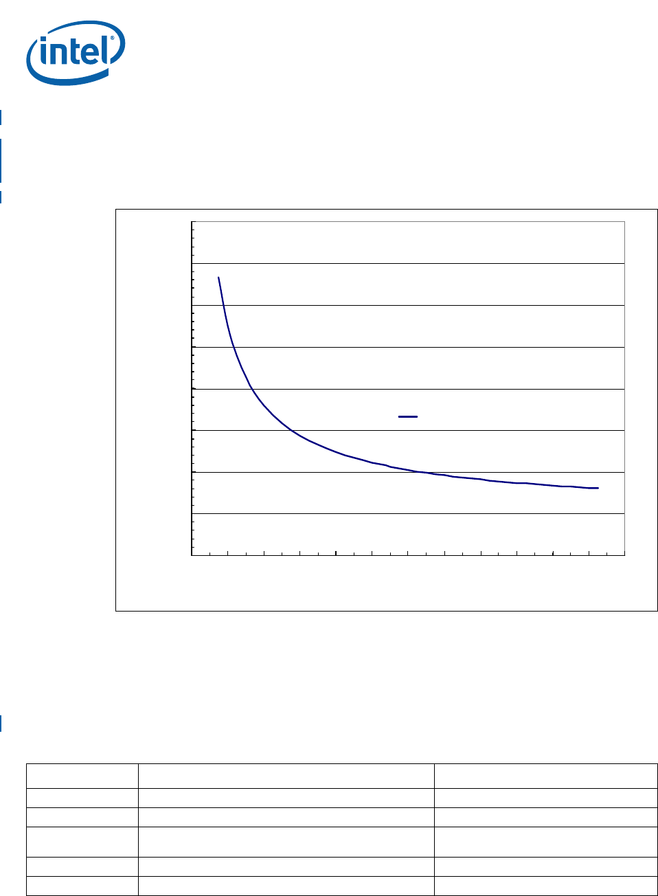
6.2.2 Thermal Solution Performance Characteristics
Figure 22 shows the performance of the CompactPCI* reference heatsink. This figure
shows the thermal performance of the heatsink versus the airflow approach velocity
provided.
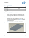
7.0 Reliability Guidelines
Each motherboard, heatsink, and attach combination may vary the mechanical loading
of the component. The user should carefully evaluate the reliability of the completed
assembly prior to use in high volume. Some general recommendations are shown in
Table 8.
Figure 22. CompactPCI* Reference Heatsink Thermal Performance
0
0.5
1
1.5
2
2.5
3
3.5
4
0 100 200 300 400 500 600 700 800 900 1000 1100 1200
Airflow Approach Velocity (LFM)
Case-To-Ambient Thermal Characterization Parameter
Ψ
ca
(
o
C/W)
CompactPCI* Heatsink
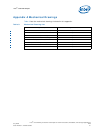
Table 8. Reliability Requirements
Test
1
Requirement Pass/Fail Criteria
2
Mechanical Shock 50 g, board level, 11 ms, three shocks/axis Visual Check and Electrical Functional Test
Random Vibration 7.3 g, board level, 45 minutes/axis, 50 Hz to 2000 Hz Visual Check and Electrical Functional Test
Temperature Life
85 °C, 2000 hours total, checkpoints at 168, 500, 1000,
and 2000 hours
Visual Check
Thermal Cycling -5 °C to +70 °C, 500 cycles Visual Check
Humidity 85% relative humidity, 55 °C, 1000 hours Visual Check
Notes:
1. The above tests should be performed on a sample size of at least 12 assemblies from three lots of material.
2. Additional pass/fail criteria may be added at the discretion of the user.