


Intel
®
5100 MCH Chipset
Intel
®
5100 Memory Controller Hub Chipset for Communications, Embedded, and Storage Applications
TDG July 2008
26 Order Number: 318676-003US
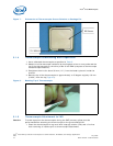
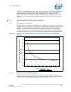
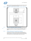
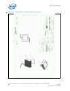
When using heatsinks that extend beyond the MCH chipset reference heatsink envelope
shown in Figure 19, any motherboard components placed between the heatsink and
motherboard cannot exceed 2 mm (0.07") in height.
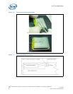
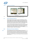
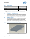
6.1.3 Board-level Components Keepout Dimensions
The location of hole patterns and keepout zones for the AdvancedTCA* reference
thermal solution are shown in Figure 25. This reference thermal solution has the same
hole patterns as that of the Intel
®
E7500 Series Chipset and Intel
®
5000 Series
Chipset.
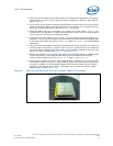
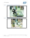
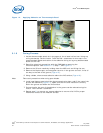
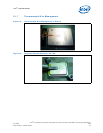
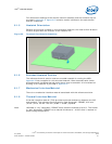
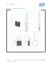
6.1.4 Torsional Clip Heatsink Thermal Solution Assembly
The reference thermal solution for the MCH is a passive extruded heatsink with a
thermal interface. It is attached using a clip with each end hooked through an anchor
soldered to the board. Figure 20 shows the reference thermal solution assembly and
associated components. The torsional clip and the clip retention anchor are the same as
the ones used on the Intel
®
E7500 Series Chipset reference thermal solution.
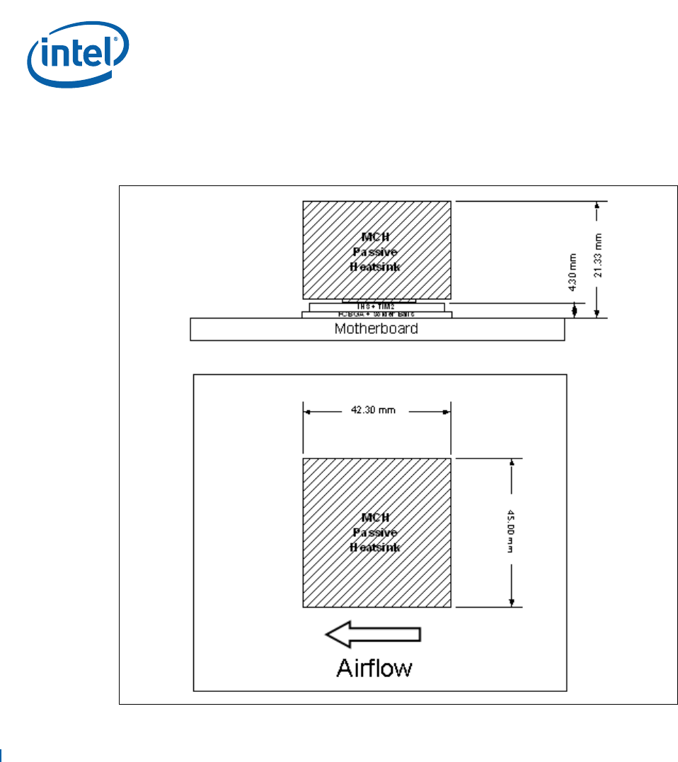
Figure 19. AdvancedTCA* Torsional Clip Heatsink Volumetric Envelope for MCH Heatsink