


INTEL 186 EB/EC EVALUATION BOARD USER’S MANUAL
2-4
2.3 VIEWING THE BOARD SCHEMATICS
The schematics provided on the diskette are in the Adobe* Acrobat .pdf format. You can view
and print the schematics using the Acrobat Reader. The Reader is available at no charge from the
Intel World Wide Web site (http://www.intel.com/) or from the Adobe site
(http://www.adobe.com/).
2.4 SETTING UP THE EVALUATION BOARD AND THE HOST PC
This section tells you how to set up the board for use with a host PC. This section assumes you
won’t be using some of the advanced features of the board when you first power it up. For
additional options, such as selecting 80188 evaluation mode, refer to Chapter 3, “Hardware
Overview.”
1. Make sure you are in a static-free environment before removing any components from
their anti-static packaging. The evaluation board is susceptible to electro-static discharge
damage; such damage may cause product failure or unpredictable operation.
2. Inspect the contents of your kit. Make sure that all items are included. Check for damage
that may have occurred during shipment. Contact your sales representative if any items are
missing or damaged.
CAUTION: Many of the connectors on the evaluation board provide power through non-
standard pins. Connecting the wrong cable or reversing the cable can damage the
evaluation board and may damage the device being connected. Use extreme
caution when preparing to connect cables to this product.
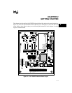
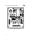
3. Connect the power supply. The Intel 186 EC/EB Evaluation Board operates from a
5 VDC ± 10% power supply plugged into the J2 power connector (see Figures 2-1
and 2-2). This 5 volt signal is stepped down to 3.3 volts on the board. The connector
housing and contact pins provided in your kit match the power supply to the J2 connector.
To select 5 V, place a jumper on pins B and C of jumper E1. To select 3 V, place a jumper
on pins A and B of jumper E1. See Figures 2-1 and 2-2 for jumper locations.
All devices on the board operate at both 3.3 volts and 5.0 volts (except the LCD display,
which is hardwired to 5 volts). This option allows comparison of current consumption
when running code at either voltage. Separately packaged 5 V versions of the 80C186
processor and SRAM must be installed on the board for 5 V operation.