


3-3
HARDWARE OVERVIEW
3
3.3 MEMORY CONFIGURATION
The memory on the evaluation board can be divided into three types: Flash, SRAM, and
expansion. Flash memory contains the Flash loader utility, located in the boot block boundary,
and the RISM monitor program, beginning at F800:0000. Users can execute their test code from
boot-up using the Flash loader utility. Refer to the CQI Flash Loader Reference Manual for
instructions on programming the Flash memory. SRAM memory is used for the processor
interrupt vector table, stack allocation, and RISM data variables, and as a possible destination for
user-written code downloaded on the host interface. Expansion memory can be accessed through
the expansion interface, if required.
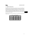
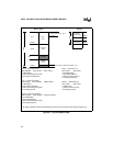
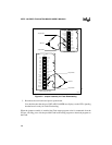
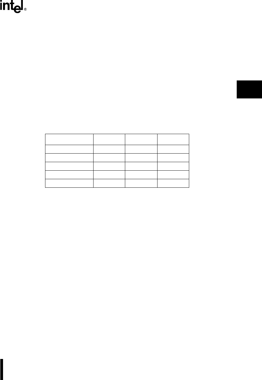
Table 3-2 shows the logical memory map and Figure 3-1 shows the physical memory map of the
evaluation board.
Table 3-2. Logical Memory Map
Memory Area Start (H) Stop (H) Size
SRAM 0000:0000 2000:0000 128 Kbytes
Flash 8000:0000 F000:FFFF 512 Kbytes
Flash Boot Block FC00:0000 F000:FFFF 16 Kbytes
Expansion 4000:0000 8000:0000 256 Kbytes
LCD (I/O) 0000:0400 0000:0440 64 bytes