


INTEL 186 EB/EC EVALUATION BOARD USER’S MANUAL
3-10
The two serial connectors are connected to the Maxim MAX561, an EIA/TIA-562
Driver/Receiver. This device operates from a 3.3 volt V
CC
(or 5 volts, optionally). The EIA/TIA-
562 standard is a low voltage serial communications protocol. This protocol operates at ±3.7
volts. The 3.3 volt signals from the board are charge-pumped to ±6.6 volt levels internally,
conforming to this standard. Signals from the serial connectors, P1 and P2, are translated to a 3.3
volt level. Output from this device is recognized by EIA/TIA-232-D receivers, and inputs can
handle EIA/TIA-232-D levels without damaging the device. The MAX561 SHDN pin (pin 25)
connects to port pin 1.0 on the 80x186 processor. When this pin is programmed to a logic 1, the
Maxim device will go into shutdown mode, reducing current consumption to leakage. During
initialization, port pin 1.0 is programmed to a logic 0 to enable communication with the host PC.
Serial communications on the evaluation board are controlled by the 80x186 processor on-chip
serial ports. Serial Port 0 on the microprocessor handles PC communications via connector P1.
Serial Port 1 is available for user applications via connector P2. The 80x186 processor supports
synchronous serial communications as well as various modes of asynchronous communications.
The time base for the host interface is a 6.0 MHz oscillator connected to BCLK0, the external
serial clock input on the 80x186 processor. This allows the user to change the processor operating
frequency without altering the baud rate.
NOTE
The BCLK0 input must be less than half the processor operating frequency
(which is half the clock input frequency). Operating the processor below
12.288 MHz requires reprogramming the serial control unit on the 80x186
processor. The source code for the RISM monitor is provided on a floppy
diskette included in your kit for this purpose.
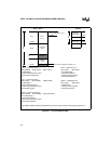
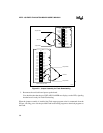
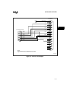
Figure 3-5 on page 3-11 illustrates the adaptor cable needed if your PC has a 25-pin serial port
connector.
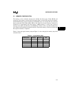
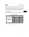
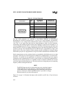
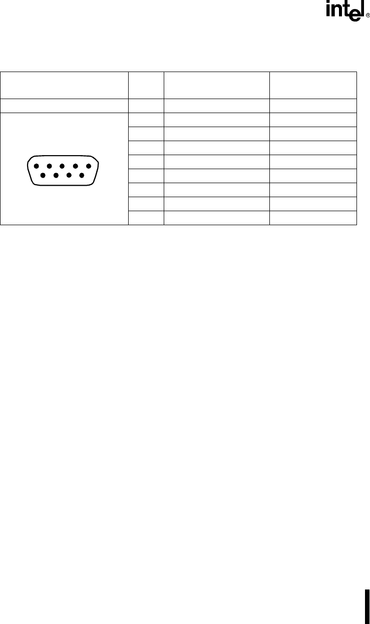
Table 3-4. P2 Serial Channel 0
P2 Connector
Pin
Nos.
Host RS-232
Signal Name
Connection on
Evaluation Board
1 (CF) DCD Data Carrier Detect Test Point 1
2 (BB) RxD Receive Data RxD
3 (BA) TxD Transmit Data TxD
4 (CD) DTR Data Terminal Ready Test Point 4
5 (AB) SG Signal Ground Digital Ground
6 (AB) DSR Data Set Ready Test Point 2
7 (CD) RTS Request To Send Test Point 3
8 (BA) CTS Clear To Send CTS
9 (BB) RI Ring Indicator Test Point 5
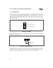
1234 5
6
78
9