


INTEL 186 EB/EC EVALUATION BOARD USER’S MANUAL
3-4
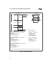
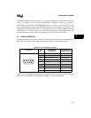
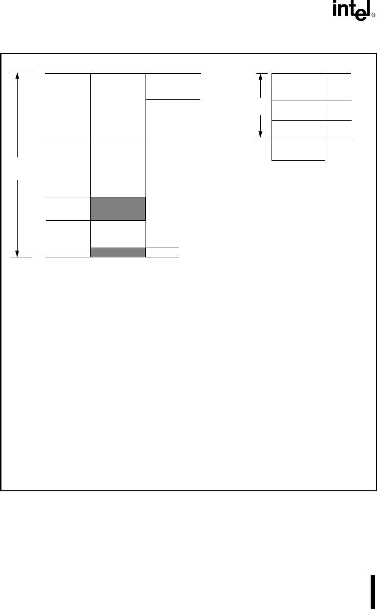
Figure 3-1. Physical Memory Map
GCS7 — Expansion I/O
Start: 400H Stop: 500H
• Zero Wait States
• Ignore Stop Address
• Active for I/O Bus Cycles
• Bus Ready Required
GCS2 — LCD Display I/O
Start: 400H Stop: 440H
• 8 Wait States
• Active for I/O Bus Cycles
• Bus Ready Ignored
1Meg
UCS Flash
512 K
GCS5
Expansion
256 K
LCS
Unused
SRAM
128 K
Interrupt Vector Table at 00000H to 003FFH (1 K)
FFFFFH
Flash Loader Utility* (16 K)
FC000H
FFFFFH
80000H
20000H
00000H
64 K
Peripheral
Control Block
LCD Control
0400H
0440H
FF00H
FFFFH
IO SpaceMemory Space
UCS — Upper Chip Select
Start: 80000H Stop: FFFFF (Flash 512 K)
• 3 Wait States
• Active for Memory Bus Cycles
• Bus Ready Not Required
LCS — Lower Chip Select
Start: 0000H Stop: 40000H (SRAM 128 K)
• 2 Wait States
• Stop Address Required
• Active for Memory Bus Cycles
• Bus Ready Ignored
GCS5 — Expansion Memory
Start: 40000H Stop: 80000H (Expansion 256 K)
• Zero Wait States
• Ignore Stop Address
• Active for Memory Bus Cycles
• Bus Ready Required
40000H
LCS
* As shipped, RISM is located at F800:0000 and pointed to by the Flash loader utility during boot-up.