


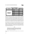

INTEL 186 EB/EC EVALUATION BOARD USER’S MANUAL
3-8
3.5 POWER SUPPLY
The power supply connects to J2 on the board schematic. Pin 1 must connect to +5 volts and pin
2 must connect to ground. The supply is then regulated to 3.3 volts by the on-board circuitry. The
V
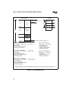
CC
for the board is controlled by jumper E1. When E1 is in the A–B position, V
CC
= 3.3 volts;
when E1 is in the B–C position, V
CC
= 5.0 volts. V
CC
is converted to +12 volts for optional Flash
programming voltage.
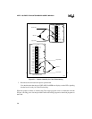
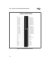
Figure 3-3. E1 Jumper
The LCD display controller V
CC
pin connects directly to the 5 volt supply, not the V
CC
plane,
allowing 5 volt operation only.
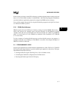
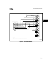
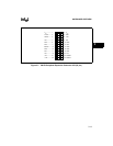
Figure 3-4. J2 Power Connector
The Maxim* MAX750 component at U6 (EC) or U7 (EB) is a current-mode DC-DC converter.
This device takes the 5 volt supply and steps it down to 3.3 volts. This voltage output is always
supplied to provide V
CC
for the processor, memory, and logic when selected at E1.
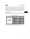
E1
A – B
B – C
C
B
A
VCC = 5.0 volts
VCC = 3.3 volts
A2607-01
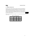
Ground - V
SS
+5VDC - V
CC
21