9
• Real-Time Clock
• On-board PCI devices
Enhanced capabilities include the ability to configure each interrupt level for active high-going edge or active
low-level inputs.
The cPB-4612's interrupt controllers reside in the 6300ESB device. The "Intel 855GME Chipset" topic in
Appendix D provides a link to the datasheet for this device.
1.3.15 Counter/Timers
Three 8254-style counter/timers, as defined for the PC/AT, are included on the cPB-4612. Operating modes
supported by the counter/timers include:
• Interrupt on count
• Frequency divider
• Software triggered
• Hardware triggered
• One shot
The cPB-4612's Counter/Timers reside in the Intel 6300ESB device. The "Intel 855GME Chipset" topic in
Appendix D provides a link to the datasheet for this device.
1.3.16 DMA
Two cascaded 8237-style DMA controllers are provided on the cPB-4612 for use by the on-board
peripherals.
The cPB-4612's DMA controllers reside in the Intel 6300ESB device. The "Intel 855GME Chipset" topic in
Appendix D provides a link to the datasheet for this device.
1.3.17 Real-Time Clock
The real-time clock performs timekeeping functions and includes 256 bytes of general-purpose, battery-
backed, CMOS RAM. Timekeeping features include an alarm function, a maskable periodic interrupt, and a
100-year calendar. The system BIOS uses a portion of this RAM for BIOS setup information.
The cPB-4612's Real-Time Clock resides in the Intel 6300ESB device. The "Intel 855GME Chipset" topic in
Appendix D provides a link to the datasheet for this device.
1.3.18 Reset
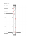
The push-button reset on the cPB-4612's faceplate functions as a "Hard Reset". See Chapter 4, "Reset," for
more information about reset sources for the cPB-4612.
1.3.19 Two-Stage Watchdog Timer
The watchdog timer optionally monitors system operation and is programmable for different timeout periods
(from 1 microsecond to 10 minutes). It is a two-stage watchdog, meaning that it can be enabled to produce a
system management interrupt (SMI) or an IRQ (APIC 1, INT 10) before it generates a Reset. Failure to
strobe the watchdog timer within the programmed time period may result in an SMI, a reset request, or both.
A register bit can be read to indicate if the watchdog timer caused the reset event. This watchdog timer
register is not cleared on power-up, enabling system software to take appropriate action if the watchdog
generated the reboot.
See Chapter 7, "Watchdog Timer," for more information, including sample code.


