75
B.6 J1 (10/100 Ethernet)
J1 is an 8-pin RJ-45 connector providing 10 Mb (10BASE-T) and 100 Mb (100BASE-TX) protocols out the
front of the board. Two LEDs are located inside each RJ-45 connector:
First LED
:
• Green indicates a link
• Blinking Green indicates activity
Second LED
:
• Off = 10 MB
• Green = 100 MB
Ethernet signals are directed out the front J1 port.
B.7 J4 (Universal Serial Bus 0 connector)
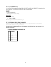
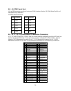
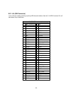
J4 (Port0) is a Universal Serial Bus (USB) Interface connector . See the "J4 Universal Serial Bus 0
Connector Pin out" table below for pin definitions.
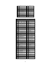
USB port 0 is only available from the front USB connector, but USB Ports 2 and 3 are routed out J5 for
use with a RPIO board.
J4 Universal Serial Bus 0 Connector Pin out
Pin# Function
1 Vcc (Fused)
2 DATA-
3 DATA+
4 GND


