22
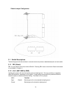
3.1.3 J16-2 (+12V to J5-pin D1).
Installing this jumper will connect +12V to the CompactPCI connector J5, pin D1. This is only to be used
for specially designed RTM cards that may need it. The default is for no jumper.
J16-2 Function
Open Default CPCI J5-pin D1 is a no connect.
Closed CPCI J5-pin D1 is shorted to +12V.
3.1.4 J16-3 (+5V PMC I/O)
Installing this jumper sets the 32bit/33Mhz PMC site’s VI/O voltage to +5V. Having no jumper sets the
VI/O voltage to 3.3V. The 32bit/33Mhz PMC site is located on the bottom edge of the board, closest to
the jumpers.
WARNING: The voltage key for the 32bit/33Mhz PMC site must be set to match this jumper setting.
Not placing the voltage key, placing the voltage key at the wrong location, or using a PMC card that is not
tolerant of the set voltage may damage the PMC card and/or the cPB-4612 board.
J16-3 CMOS Real Time Clock
Open Default 32bit/33Mhz PMC site set to 3.3V.
Closed 32/bit/33Mhz PMC site set to 5V.
3.1.5 J16-4 (IMPI Disable)
This is for debug use only. Placing this jumper will disable the IMPI controller. This should only be used
by the manufacturer.
J16-4 CMOS Real Time Clock
Open Default Normal Operation
Closed IMPI controller disabled
3.1.6
J17-1 (Not Used)
Not used
J17-1 Function
Open Default Not used
Closed Not used
3.1.7 J17-2 (CMOS Clear)
Installing this jumper will reset the CMOS settings to their default values.
J17-2 Function
Open Default Normal operation
Closed Clears CMOS and sets registers to their default state.


