68
Appendix
B
B
B Connectors
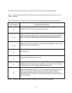
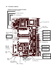
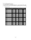
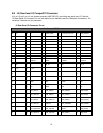
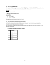
As shown in the "Connector Locations" figure, the cPB-4612 includes several connectors to interface to
application-specific devices. A brief description of each connector is given in the "Connector
Assignments" table below. A detailed description and pin out for each connector is given in the following
topics.
Connector Assignments
Connector Function
J15 CompactPCI Bus Connector (110-pin, 2 mm x 2 mm, female)
J11 CompactPCI Bus Connector (110-pin, 2 mm x 2 mm, female)
J8 CompactPCI (Ethernet) Connector (95-pin, 2 mm x 2 mm, female)
J2 Rear-panel I/O Connector (110-pin 2 mm x 2 mm, female)
J1 10/100 Ethernet (8-pin)
J3 COM1 Serial Port (9-pin)
J4 Universal Serial Bus Connector (4-pin, USB, Port 0)
J6, J7, J9, J10 64bit/66Mhz PCI Mezzanine Connector(s) (64-pin, 1 mm)
J12, J13 32bit/33Mhz PCI Mezzanine Connector(s) (64-pin, 1 mm)
J14 IDE Connector (primary channel – local hard drive)
U22, U25 Right angle DIMM connector


