


ECB-865
ECB-865 User’s Manual 35
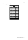
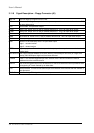
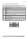
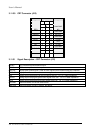
3.11.13 Signal Description – Parallel Port Connector (J11)
The following signal description covers the signal definitions, when the parallel port is
operated in standard centronic mode. The parallel port controller also supports the fast
EPP and ECP modes. Please refer to reference 2 for further information.
PD7..0 Parallel data bus from PC board to printer. The data lines are able to operate in PS/2
compatible bi-directional mode.
SLIN# Output line for detection of printer selection. This pin is pulled high internally.
SLCT An active high input on this pin indicates that the printer is selected. This pin is pulled high
internally.
STB# An active low output is used to latch the parallel data into the printer. This pin is pulled high
internally.
BUSY An active high input indicates that the printer is not ready to receive data. This pin is pulled
high internally.
ACK# An active low input on this pin indicates that the printer has received data and is ready to
accept more data. This pin is pulled high internally.
INIT# Output line for the printer initialization. This pin is pulled high internally.
AFD# An active low output from this pin causes the printer to auto feed a line after a line is printed.
This pin is pulled high internally.
ERR# An active low input on this pin indicates that the printer has encountered an error condition.
This pin is pulled high internally.
PE An active high input on this pin indicates that the printer has detected the end of the paper.
This pin is pulled high internally.
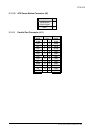
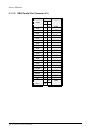
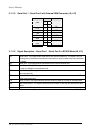
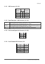
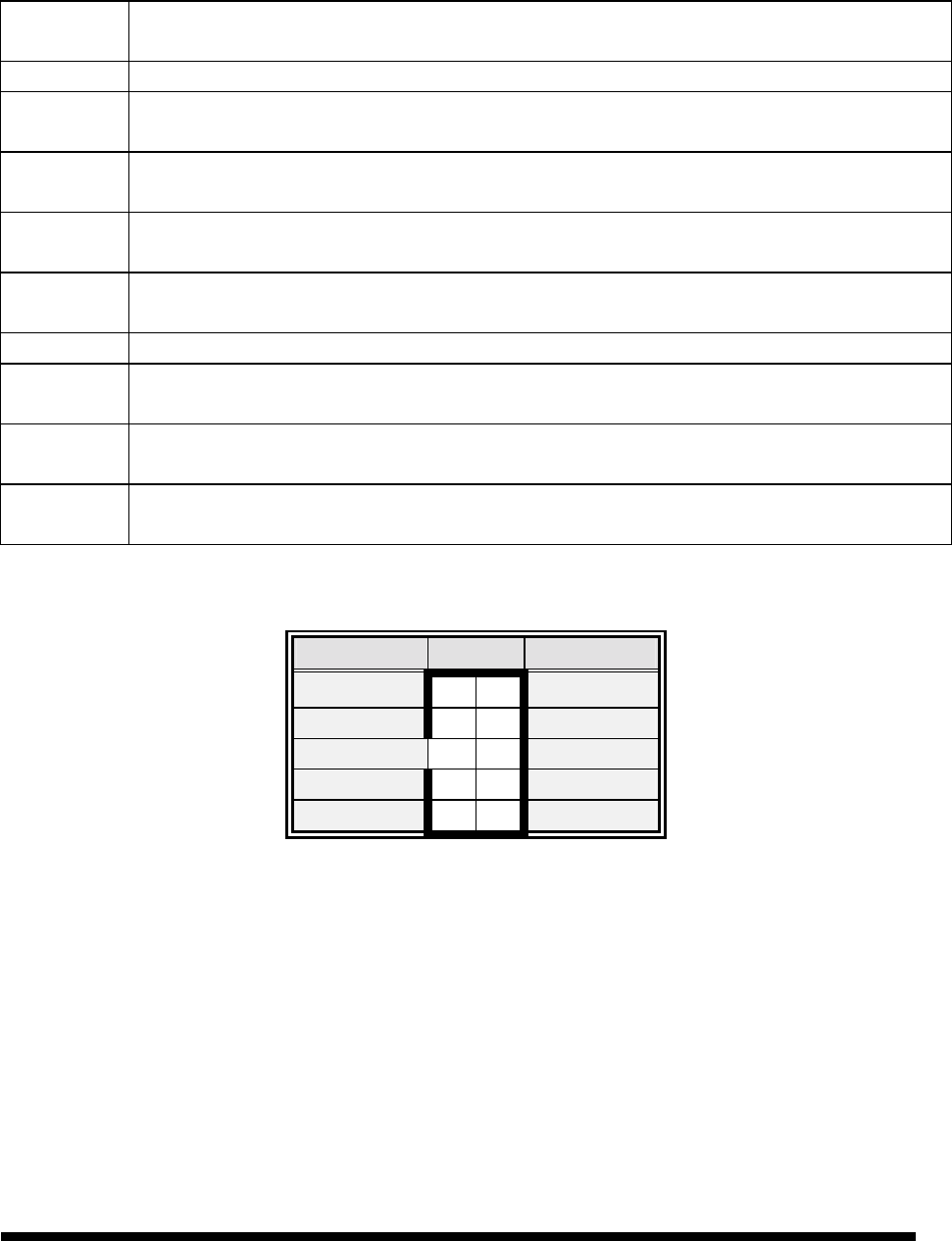
3.11.14 Box Header Serial Port 1 / Serial Port 2 Connector in RS-232 (J9, J12)
Signal PIN Signal
DCD 1 2 RxD
TxD 3 4 DTR
GND 5 6 DSR
RTS 7 8 CTS
RI 9 10 NC