ECB-865
ECB-865 User’s Manual 37
3.11.17 Box Header Serial Port 1 / Serial Port 2 Connector in RS-422 (J9, J12)
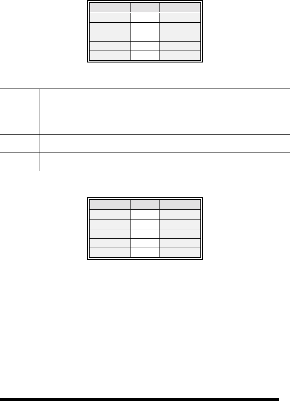
Signal PIN Signal
NC 10 9 RI
CTS 8 7 RTS
DSR 6 5 GND
TxD+ 4 3 TxD-
RxD- 2 1 RxD+
3.11.18 Signal Description – Serial Port 1 / Serial Port 2 in RS-422 Mode (J9, J12)
TxD +/- Serial output. This differential signal pair sends serial data to the communication link. Data is
transferred from Serial Port 2 Transmit Buffer Register to the communication link, if the TxD
line driver is enabled through the Serial Port 2’s DTR signal. (Modem control register)
RxD +/- Serial input. This differential signal pair receives serial data from the communication link.
Received data is available in Serial Port 2 Receiver Buffer Register.
RTS +/- Request To Send. The level of this differential signal pair output is controlled through
the Serial Port 2’s RTS signal (Modem control register).
CTS +/- Clear To Send. The level of this differential signal pair input could be read from the Serial Port
2’s CTS signal. (Modem control register)
3.11.19 Box Header Serial Port 1 / Serial Port 2 Connector in RS-485 (J9, J12)
Signal PIN Signal
NC 10 9 CTS/RTS +
NC 8 7 CTS/RTS -
NC 6 5 GND
RxD/TxD + 4 3 RxD/TxD -
NC 2 1 NC


