


APPENDIX C
Cable Pinouts
C-4
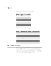
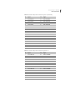
Table C-3 lists the pinout for the crossover adapter.
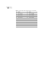
Table C-4 lists the pinout for the straight-through adapter.
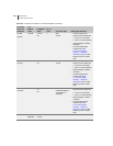
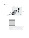
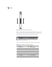
CT1 and CE1 I/O Modules
CT1 I/O modules have 24 RJ-48C female connectors. CE1 I/O modules
have either 20 RJ-48C female connectors or two 25-pair female Telco
connectors. Figure C-3 shows the location of the ports on a CT1 I/O
module and the sequence of the pins in the RJ-48C connector. CE1 I/O
modules equipped with RJ-48C connectors have the same configuration
as CT1 I/O modules equipped with RJ-48C connectors.
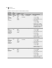
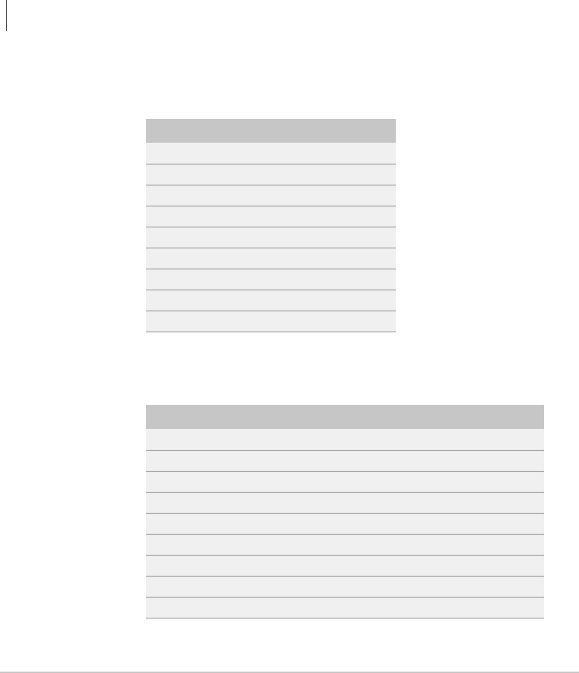
Table C-3 DB-9 – RJ-45 crossover adapter pinout
DB-9 Pin Signal RJ-45 Pin
1 DCD 1
2 RXD 3
3 TXD 2
4 DTR 6
5 GND 5
6 DSR 4
7 RTS 8
8 CTS 7
9 RNG n/c
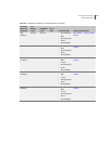
Table C-4 DB-9 – RJ-45 straight-through adapter pinout
DB-9 Pin RS-232 Signal Name RJ-45 Pin Ethernet Signal Name
1 DCD 1 TX +
2 RXD 2 TX –
3 TXD 3 RX +
4 DTR 4 n/c
5 GND (signal) 5 n/c
6 DSR 6 RX –
7 RTS 7 n/c
8 CTS 8 n/c
9 RNG n/c none