


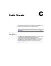
CT1 and CE1 I/O Modules
ERX Edge Routers
C-5
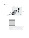
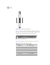
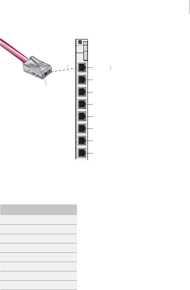
Figure C-3 CT1 I/O module ports
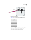
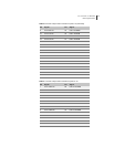
Table C-5 lists the pinout for the CT1/CE1 connector.
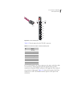
For CE1 I/O modules with Telco connectors, the other ends of the cables
are attached to a balun panel that splits the signals from two Telco
connectors to 20 pairs of BNC connectors. We supply the Telco cables if
you purchase a balun panel. Figure C-4 shows the location of the Telco
connectors on a CE1 I/O module and the sequence of the pins in the
connectors.
Table C-5 CT1/CE1 I/O module – RJ-48C connector pinout
Pin Signal
1 RX Ring
2 RX Tip
3 n/c
4 TX Ring
5 TX Tip
6 n/c
7 n/c
8 n/c
CT1
I/O
Port 0
Port 1
Port 2
Port 3
Port 4
Port 5
Port 6
PIN 1
PIN 8
PIN 1
PIN 1
PIN 8
Port 7