


APPENDIX C
Cable Pinouts
C-6
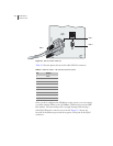
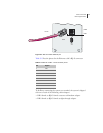
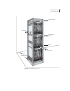
Figure C-4 CE1 I/O module with Telco connectors
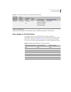
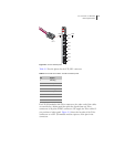
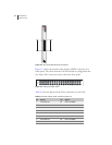
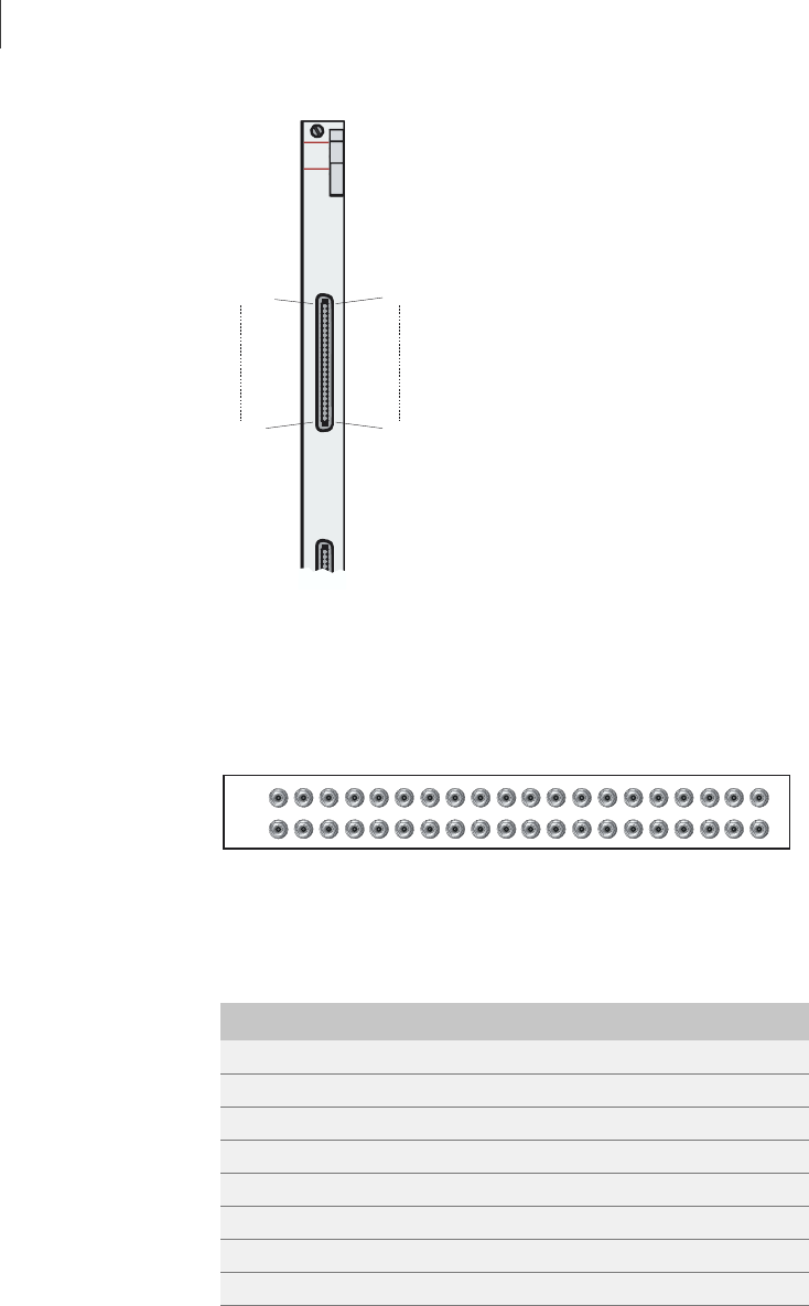
Figure C-5 shows the location of the 20 pairs of BNC connectors on a
balun panel. The cables from the CE1 I/O module are plugged into the
two 50-pin Telco connectors on the other side of the panel.
Figure C-5 Twenty-port balun panel
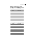
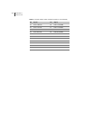
Table C-6 lists the pinout for the Telco connectors on each cable.
CE1
I/O
0-9
10-19
PIN 25
PIN 1
PIN 50
PIN 26
CE1
I/O
0-9
10-19
PIN 25
PIN 1
PIN 50
PIN 26
10
TX
RX
PORT
3456789 111213141516171819
1 2
0
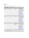
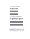
Table C-6 Pinout of 50-pin Telco connector to ports 0–9
Pin Signal Pin Signal
1 Port 0 RX TIP 26 Port 0 RX RING
2 Port 0 TX TIP 27 Port 0 TX RING
3 Port 1 RX TIP 28 Port 1 RX RING
4 Port 1 TX TIP 29 Port 1 TX RING
5 Port 2 RX TIP 30 Port 2 RX RING
6 Port 2 TX TIP 31 Port 2 TX RING
7 Port 3 RX TIP 32 Port 3 RX RING
8 Port 3 TX TIP 33 Port 3 TX RING