


Cabling the SRP I/O Module
ERX Edge Routers
4-7
Cabling the SRP I/O Module
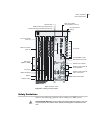
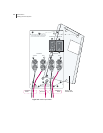
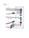
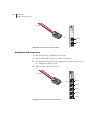
The next step in cabling the system is to connect cables to your SRP I/O
module. See Figure 4-3.
Note: The alarm function on the SRP I/O module is currently not implemented.
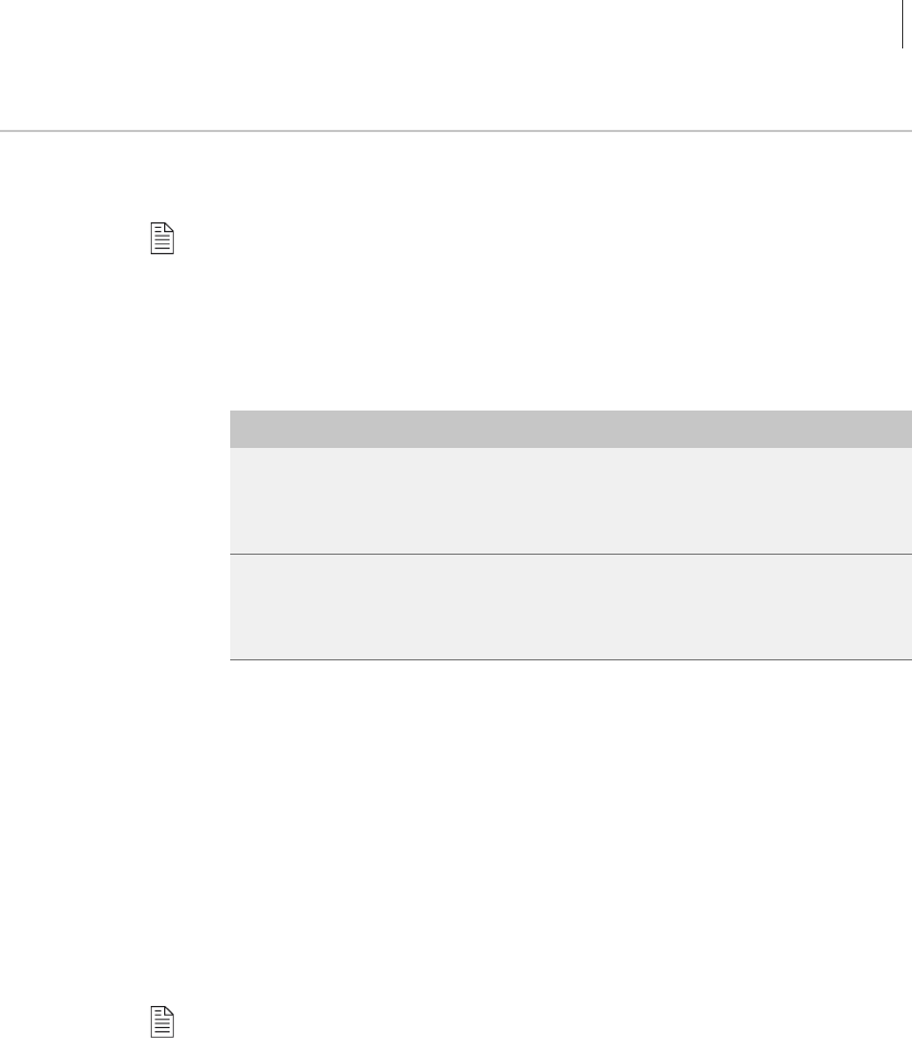
Cable connections to your SRP I/O module are divided into two sections:
external timing ports and console ports. Table 4-2 shows the
specifications for each section.
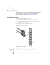
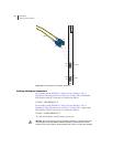
External Timing Ports
Two external clock source input ports provide a method of ensuring that
the system’s clock timing remains synchronized with the network’s system
clock. The primary clock is labeled A; the secondary, redundant clock is
labeled B. Use the connector type appropriate for your location:
• Two 75-ohm E1 2.048-Mbps inputs with BNC connectors
• Two 100-ohm T1 inputs with three pin wire-wrap connectors. Pins are
labeled T (Tip), G (Ground), and R (Ring). We recommend using
26-AWG wire minimum.
Note: Use shielded cables to connect the external clock sources to the clock
source input ports.
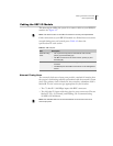
Table 4-2 SRP I/O ports
Port Description
External Timing
Ports
• Two 3-pin wire-wrap posts for US external clock sources;
primary (A) and secondary (B)
• Two BNC connectors for E1 clock sources; primary (A) and
secondary (B)
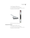
Console Ports • One 10/100Base-T Ethernet management port with an RJ-48C
connector
• One RS-232 port with a DB-9 connector for VT100 management
access