


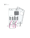

Cabling the Power Input Module
ERX Edge Routers
4-5
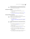
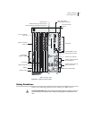
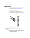
Follow the procedure in this section to connect power cables to the
system. Refer to Figure 4-2 as needed.
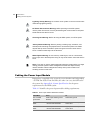
Caution: Before you begin this procedure, ensure that both Power A and Power B
switches are in the OFF position.
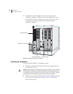
1 Loosen the four screws from the clear power input module cover.
2 Remove the cover by sliding it upward so that the screw heads line
up with the holes in the cover.
3 Set the cover and screws aside for later use.
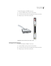
4 Connect the ground wire to the ground terminal on the lower
portion of the power input module, and secure it with a #10 kep nut.
Note: We recommend a minimum of 10-AWG ground wire with a ring-style
terminal.
5 Connect the other end of the ground wire to the appropriate ground
termination lead.
Warning: Be sure the power source is turned off and the ERX system is turned off
before continuing with this procedure.
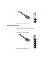
6 With the wrench or nut driver, loosen the 3/8" hex nuts from the
bottom –48 VDC and RTN leads of Power A, and connect a
10-AWG wire to each.
7 With the wrench or nut driver, tighten the hex nuts on both leads.
8 Attach the opposite end of Power A’s wire leads to the appropriate
leads on your power source.
Note: To provide redundancy, Power A and Power B leads should not terminate at
the same power source.
9 Repeat Steps 6–8 for Power B.
10 Reattach the clear power input module cover that you removed in
step 1 by securing the four screws.