


13
ENGLISH
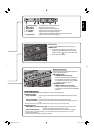
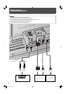
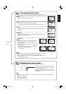
Note for VIDEO IN A (IN, Y/C IN) terminals
When both IN terminal and Y/C IN terminal are used, the input to the Y/C IN terminal has priority.
Note for VIDEO IN B (RGB/COMPO., DVI-D) terminals
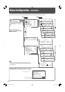
Select the correct input for Input B on the main menu (see “INPUT CONFIGURATION” on page 23).
• When RGB signals are input to the RGB/COMPO. terminal: Set “INPUT B” to “ANALOG RGB.”
• When component signals are input to the RGB/COMPO. terminal: Set “INPUT B” to “COMPONENT.”
• When using the DVI-D terminal: Set “INPUT B” to “DVI.”
Note for component signals
• The monitor is compatible only with Y on sync signals. The monitor is not compatible with composite sync (Cs) and
separated sync (HD/VD) signals.
Note for computer signals
• When analog RGB signals are input, part of the picture may not be displayed or an unnecessary picture may appear in the
following cases. Adjust size and position in the “SIZE SETTING” menu (see page 21).
– When a signal other than those listed on page 12 is input
– When the horizontal/vertical frequency of the signal is different though its resolution is the same as that of the signals
listed on page 12
– When the resolution of the signal output from the personal computer is different from that set for the personal
computer’s display.
• Any signal other than those listed on page 12 may not be displayed normally although it’s frequency is within the
acceptable range.
• Depending on the connected equipment, the monitor may not be compatible with composite sync (Cs) or G on sync
signals.
• When a preset mode signal is input, the signal format is displayed on the screen. For other signals, the horizontal/vertical
frequency or resolution is displayed.
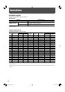
• The DVI-D terminal can accept only No. 3, 4, 6 – 11, 16, 18, and No. 19 signals.
•
When the No. 3 and No. 7 signals are input, set the video card of the personal computer to “640 x 480” (for No. 3 signal)/
“1024 x 768” (for No. 7 signal). For analog RGB input, also set “SAMPLING MODE” to “STD” on the set-up menu (see page 31).
• When the No. 4 and No. 8 signals are input, set the video card of the personal computer to “852 x 480” (for No. 4
signal)/“1366 x 768” (for No. 8 signal).
For analog RGB input, also
set “SAMPLING MODE” to “WIDE” on the set-up menu (see
page 31), and then change the aspect ratio to “FULL” (see pages 17 and 21).
• When No. 15 to No. 20 and No. 24 signals are input, thin lines may become obscured because their signal frequencies are
higher than the screen resolution.
• When the No. 16 signal is input, set the video card of the personal computer to “1280 x 1024.” For analog RGB
input
, also set
“SXGA/SXGA+” to “SXGA” on the set-up menu (see page 31).
• When the No. 18 and No. 19 signals are input, set the video card of the personal computer to “1400 x 1050.” For analog RGB
input
, also set “SXGA/SXGA+” to “SXGA+” on the set-up menu (see page 31).
06-42_GM-H40L2A-f.indd 1306-42_GM-H40L2A-f.indd 13 06.4.24 5:20:14 PM06.4.24 5:20:14 PM