


XPort® Pro Lx6 Embedded Device Server User Guide 40
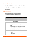
8: Configurable Pin Manager
The Configurable Pin Manager is responsible for assignment and control of the configurable pins
(CPs) available on the XPort Pro Lx6 embedded device service. There are three configurable pins
on the XPort Pro Lx6.
You must configure the CPs by making them part of a group. A CP Group may consist of one or
more CPs. This increases flexibility when incorporating the XPort Pro Lx6 into another system.
Note: The blue text in the XML command strings of this chapter are to be replaced with
a user-specified name.
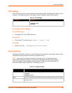
CPM: Configurable Pins
Each CP is associated with an external hardware pin. CPs can trigger an outside event, like
sending an email message or starting Command Mode on a serial Line.
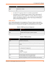
The Current Configuration table shows the current settings for each CP.
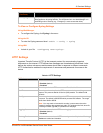
Table 8-1 Current Configurable Pins
Table 8-2 CP Status
CP Ref Configured as Value Groups Active in group
CP1 Pin 14 Input 1 2 <available>
CP2 Pin 16 Input 1 0 <available>
CP3 Pin 18 Input 0 2 <available>
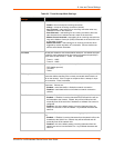
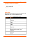
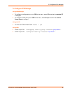
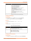
CPM – CPs Status Description
Name
Shows the CP number.
State
Shows the current enable state of the CP.
Type Shows the CP hardware pin type. Can be updated. Choices are:
Input
Output
When a CP is configured as output, it can be toggled by setting the value.
Whatever value is given, the first bit 0 is used as the setting. 1 means asserted
and 0 means de-asserted. Additionally, the CP logic can be inverted so that
assertion is low.
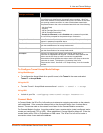
Value Shows the last bit in the CP current value.
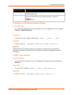
Bit
Visual display of the bitwise 32 bit placeholders for a CP.
Level
A “+” symbol indicates the CP is asserted (the voltage is high). A “-“indicates the
CP voltage is low.
I/O
Indicates the current status of the pin:
I = input
O = output
<blank> = unassigned
Logic
An “I” indicates the CP is inverted (active low).