


8: Configurable Pin Manager
XPort® Pro Lx6 Embedded Device Server User Guide 41
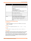
Notes:
To modify a CP, all groups in which it is a member must be disabled.
The changes to a CP configuration are not saved in FLASH. Instead, these CP
settings are used when the CP is added to a CP Group. When the CP Group is
saved, its CP settings are saved with it. Thus, a particular CP may be defined as
"Input" in one group but as "Output" in another. Only one group containing any
particular CP may be enabled at once.
CPM: Groups
The CP Groups settings allow for the management of CP groups. Groups can be created or
deleted. CPs can be added to or removed from groups. A group, based on its state, can trigger
outside events (such as sending email messages). Only an enabled group can be a trigger.
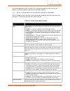
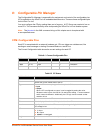
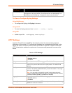
Table 8-3 CPM Group Current Configuration
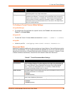
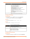
Table 8-4 CPM Group Status
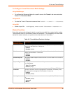
Binary
Shows the binary assertion value of the corresponding bit.
CP#
Shows the CP number.
Groups
Lists the groups in which the CP is a member.
CPM – Groups Current
Configuration
Description
Group Name Shows the CP group’s name.
State Indicates whether the group is enabled or disabled.
CP Info Shows the number of CPs assigned to the group.
CPM – Groups Group
Status
Description
Name Shows the CP Group name.
State Current enable state of the CP group.
Value Shows the CP group’s current value or shows “Disabled” if the group is
disabled.
Bit Visual display of the bit placeholders for a CP.
Level A “+” symbol indicates the CP’s bit position is asserted (the voltage is high).
A “-“ indicates the CP voltage is low.
I/O Indicates the current status of the pin:
I = input
O = output
<blank> = unassigned
Logic An “I” indicates the CP output is inverted.
Binary Shows the assertion value of the corresponding bit.
X = group is disabled or bit is unassigned in group
CP# Shows the configurable pin number and its bit position in the CP group.
CPM – CPs Status Description