


Overview
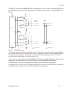
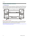
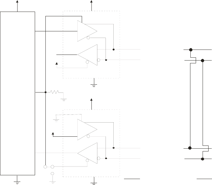
The NET485 can handle both RS485 and RS422 communications. This is done by connecting the XPort to a
pair of RS485 transceivers. The following schematic demonstrates how the circuit is wired for RS422 and
RS485.
D
R
Vcc
3.3V
DE
DI
RO
RE
GND
8
3
4
1
2
5
7
6
6
D
R
Vcc
3.3V
DE
DI
RO
RE
GND
8
3
4
1
2
5
7
6
TXDA (Pin 7)
TXDB (Pin 6)
RXDA (Pin 5)
RXDB (Pin 4)
3.3V
CP1
TX
4
RX
5
XPort 485
Vcc
3.3V
2
GND
1
3.3V
RS422
Half-Duplex
Mode
TXDA (Pin 7)
SGND (Pin 3)
RS485
Mode
TXDB (Pin 6)
RXDA (Pin 5)
RXDB (Pin 4)
SGND (Pin 3)
2
1
3
R13
10K
U2
U4
J2
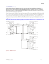
Figure 1 - RS485 Transceiver
The transmit section of the XPort is labeled TX on pin 4. The receive section of the XPort is labeled RX on
pin 5. Note that the CP1 pin on the XPort pin 6, which is configured to control the level of RS485_TXEN, is
connected to both transceivers. The transmit section is enabled with a High signal on pin 3, U2 and the
receive section is enabled with a Low signal on pin 2, U4.
There is a jumper option J2 that permits RS485/RS422 Half Duplex or RS422 Full Duplex. With the jumper
in the factory set position between pins 2 and 3, the unit is set for RS485/RS422 Half Duplex.
For RS422 mode, use the four signals produced by the two transceivers plus a signal ground.
For RS485 mode, the TXDA signal is jumpered to the RXDA terminal, and the TXDB signal is jumpered to
the RXDB terminal. The three signals are TXDA, RXDB, and signal ground.
NET485 User Guide 1-3