


Overview
1.3 RS422 / RS485 Network connections
1.3.1 RS422 Networks
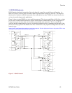
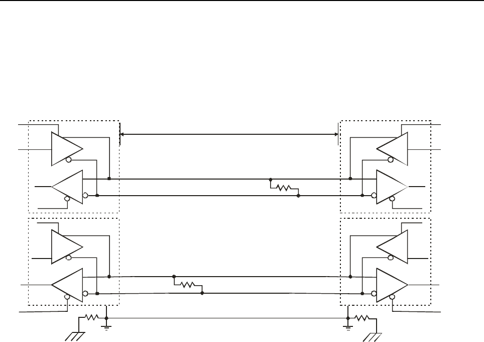
A typical RS422 application uses a four-wire interface (two twisted pairs) and a shield. RS422 networks are
often used in a half-duplex mode, where a single master in a system sends a command to a slave device and
the slave responds with data. Typically one device (node) is addressed by the host computer and a response
is received from that device. Systems of this type (4-wire, half-duplex) are often constructed to avoid "data
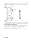
collision" (bus contention) problems on a network. Figure 2 shows a typical RS422 four wire interface.
D
R
DE
DI
RO
D
R
DE
DI
RO
CP1
TX
RX
TXDA (Pin 7)
RXDB (Pin 4)
SGND (Pin 3)
CP1
DE
CP1
D
R
DI
RO
TX
TXDA
RXDB
SGND
D
R
DE
DI
RO
RX
CP1
TXDB (Pin 6)
TXDB
RXDA (Pin 5)
RXDA
4000 ft.
Rt
Rt
Rg Rg
Figure 2 - RS422 Four Wire Interface
Notice that 5 conductors are used (two twisted pairs and a ground wire). Also, when the cable lengths are
long and/or the data rates are high, the network must be terminated. To terminate the network, a resistor Rt
is added in parallel with the receiver’s A and B lines. Rg is an optional resistor between ground and the
shield. Rt termination resistors are available as option jumpers on the NET485.
Note: Do NOT install termination resistors on short wire networks. See the Application Notes on the product CD for more
information about networks and termination procedures.
1-4 NET485 User Guide