


Introduction
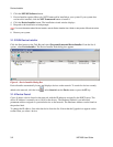
2.2 Serial RS422/485 Interface
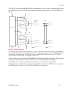
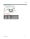
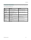
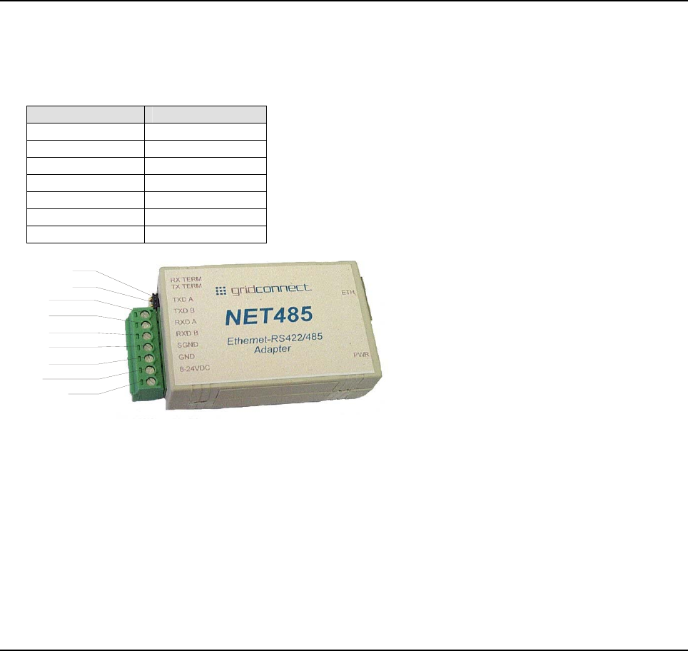
The table below lists the RS422/485 signals for the NET485. The RS422/485 and power interface is a 7-pin
removable Phoenix connector, with two of the pins used for power.
Table 1 - RS422/485 Signals
NET485 Signal 7-Pin Phoenix
TXDA 7
TXDB 6
RXDA 5
RXDB 4
SGND 3
GND 2
8-24VDC 1
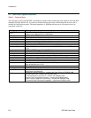
8-24VDC
GND
SGND
RXDB
RXDA
TXDB
TXDA
TX TERM
RX TERM
Figure 5 - Phoenix Connector
The NET485 uses protective clamping structures on its inputs and outputs that clamp the voltage to a safe
level and dissipate the energy present in ESD (electrostatic) and EFT (electrical fast transients) discharges.
This protection structure achieves ESD protection up to 8 kV according to IEC1000-4-2, and EFT protection
up to 2 kV on all input/output (I/O) lines.
The NET485 has jumper terminals for adding termination resistors to the RX and TX lines. Add these
jumpers ONLY if you have long transmission lines and termination resistors are needed.
Note: Do NOT use RX Term and TX Term jumpers on short transmission lines. Remove these jumpers to remove the
120 Ohm resistors from the transmit and receive lines.
Note: See the Application Notes on the product CD for more information about networks and termination procedures.
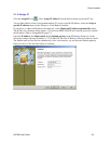
2.3 Power Supply
The NET485 can use any DC power source from 8VDC to 24VDC. The current draw is determined by
network activity and serial port communications. In general, a 500ma supply will handle the load.
Most modular power supplies use the same style of designating which lead is positive and which one is
negative. Generally, the lead with a white stripe, or white markings, is the positive lead. Verify the lead
markings with a meter before connecting a power source to the NET485.
Connect the positive lead to the terminal marked 8-24VDC. Connect the negative lead to the terminal
marked GND. See Figure 5 for lead identification. The power LED will come on when power is supplied.
See Figure 4 and Figure 6 for the location of the Power LED.
The unit will go through a self-test and will attempt to connect to a server. The LEDs on the Ethernet
connector will indicate the connection status. See Ethernet Interface.
2-2 NET485 User Guide