Monitor Mode
4. Monitoring the Network
Monitor Mode is a command-line interface used for diagnostic purposes.
4.1.1 Entering Monitor Mode via the Network Port
To enter Monitor Mode using a Telnet connection:
1. Establish a Telnet session to the configuration port (9999). The following message appears:
MAC address 00204A0113A3
Software version 01.8 (040806) XPT485
Press Enter to go into Setup Mode
2. Type M (upper case). The following message appears:
*** NodeSet 2.0 ***
A 0> prompt indicates that you have successfully entered Monitor Mode.
4.1.2 Monitor Mode Commands
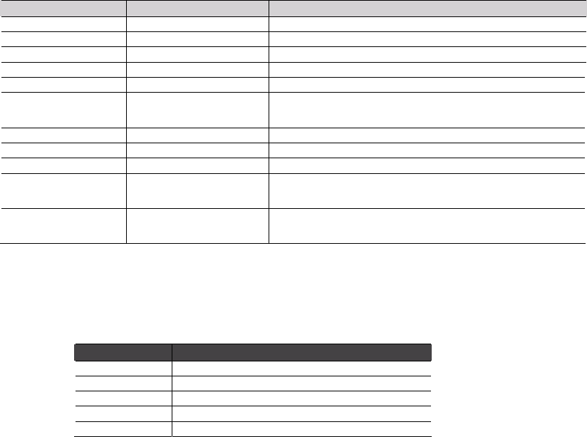
The following commands are available in Monitor Mode.
Note: All commands must be in capital letters.
Command Command Name Function
VS
Version Queries software header record (16 bytes) of unit.
GC
Get Configuration Gets configuration of unit as hex records (120 bytes).
SC
Send Configuration Sets configuration of unit from hex records.
PI x.x.x.x
Ping Pings unit with IP address x.x.x.x to check device status.
AT
ARP Table Shows the unit’s ARP table entries.
TT
TCP Connection
Table
Shows all incoming and outgoing TCP connections.
NC
Network Connection Shows the unit’s current IP address.
RS
Reset Resets the unit.
QU
Quit Exits diagnostics mode.
G0 to G8
Get configuration
from memory page
Gets a memory page of configuration information from the
device.
S0 to S8
Set configuration to
memory page
Sets a memory page of configuration information on the
device.
Responses to some of the commands are given in Intel Hex format.
Note: Entering any of the commands listed above generates one of the following command response codes:
Command Response Codes
Response Meaning
0> OK; no error
1> No answer from remote device
2> Cannot reach remote device or no answer
8> Wrong parameter(s)
9> Invalid command
NET485 User Guide 4-1


