


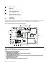

• “1090 PCI Express Mini Card for wireless WAN” on page 79 or “1090 mSATA solid state drive” on page 81
• “1100 Keyboard bezel assembly” on page 82
• “1110 Bluetooth daughter card” on page 84
• “1120 Backup battery” on page 85
• “1130 Smart Card or Smart Card dummy spacer” on page 86
• “1140 Speaker assembly” on page 88
• “1150 Thermal module” on page 89
• “1170 LCD unit” on page 93
• “1180 Base cover assembly” on page 96
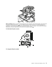
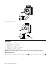
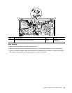
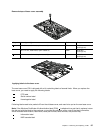
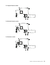
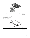
Removal steps of I/O sub card
2
1
1
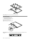
Step Screw (quantity) Color
Torque
1
M2 × 7 mm, wafer-head, nylon-coated (2) Silver
0.181 Nm
(1.85 kgf-cm)
When installing: Make sure that the connector is attached rmly.
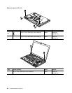
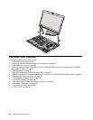
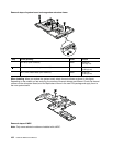
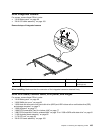
1200 System board assembly, magnesium structure frame, and modem
daughter card (MDC)
Note: The system board does not contain the Ethernet port, the ac power connector, and the modem port.
For the Ethernet port, see “1190 I/O sub card” on page 98. The ac power connector is installed on the
magnesium structure frame. If the computer is equipped with an MDC, the modem port is also installed on
the magnesium structure frame.
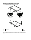
For access, remove these FRUs in order:
• “1010 Battery pack” on page 66
• “1020 Serial Ultrabay Enhanced device or travel bezel” on page 67
• “1030 DIMM slot cover” on page 68
• “1040 DIMM (bottom slot)” on page 69
• “1050 Hard disk drive slot cover, hard disk drive (HDD) and HDD rubber rails or solid state drive (SSD)
and storage converter” on page 71
• “1060 Keyboard” on page 72
• “1070 DIMM (upper slot)” on page 76
• “1080 PCI Express Mini Card for wireless LAN” on page 77
• “1090 PCI Express Mini Card for wireless WAN” on page 79 or “1090 mSATA solid state drive” on page 81
• “1100 Keyboard bezel assembly” on page 82
Chapter 9. Removing and replacing a FRU 99